
Installation
How to Repair a Cut Fiber Optic Cable in the Field
A cut fiber optic cable is not a splicing problem. It is a cable problem, and the splice is only the middle of it. The jacket that kept water out is gone, the strength member that carried the load is gone, and the closure that held the joint is gone — restore only the glass and you have scheduled the next outage for the first wet week.
That distinction is what separates a restoration from a repair, and it changes the order of operations. Before any fiber is stripped, you have to know whether the cable is even the fault. Before you cut, you have to know which restoration method you are committing to. And after you splice, you have to prove the span is back inside its loss budget and write down what you changed.
This page is the operator's procedure: five steps, with the decision that governs each one. The instrument techniques it refers to — how to run the tester, how to make the splice — are covered in depth in the rest of the installation, splicing and testing handbook; this page is what you do when one of its cables has already been cut.
What a Cut Fiber Optic Cable Actually Is
"Cut" is used for four different failures, and they are not interchangeable.
Failure | What is broken | What it usually means |
|---|---|---|
Cable cut | Fibers, jacket and strength member across the whole cable | A section must be spliced back together inside a new closure |
Single fiber break | One fiber in a tray, closure or splice protector | Switch to a spare fiber, then repair the splice at the next window |
Connector / patchcord failure | Endface contamination, a damaged ferrule, a strained patchcord | Re-terminate or replace; the cable is untouched |
Not the plant at all | Failed power, a dead optic, a wrong port, a polarity swap | Nothing to splice — and this is the most expensive thing to misdiagnose |
The fourth row is the reason Step 1 exists. Restorations that run long are usually restorations that were opened before the fault was confirmed, and a crew that has already cut the jacket is committed to a splice whether the cable needed one or not.
Where a cable gets cut is mostly a matter of how it was built and where it was run, and it decides how hard the repair is:
- Buried outside plant (OSP). Dig-ups and directional boring are the classic causes — "backhoe fade" is the industry's own name for it. The cable is often deep enough to survive weather and shallow enough to be found by a bucket.
- Aerial. Gunshots, rodents, storm and ice loading, and vehicles hitting poles. Aerial damage is frequently partial: a kinked or crushed span with high loss but intact glass, which tests as a bad span and is not actually severed.
- Premises and last mile. Damage happens during moves, adds and changes — abandoned cable being pulled out of trays, a riser cable kinked around a corner, a drop jumper crushed in a door. A cut fiber-to-the-home (FTTH) drop cable in a duct usually does not need a closure at all; it needs a decision (Step 3).
Whatever the location, restoration has three deliverables, not one: the glass joined, the cable sealed, and the record updated. Most write-ups of fiber optic cable repair stop at the first.
And the cheapest restoration is the one that never has to happen. A network designed with route diversity between two geographically separate paths, or with a dual link and protection switching that moves traffic in milliseconds, turns a cut from an outage into a log entry. Where neither exists, the next best thing is already on the shelf: spare fibers in the cable, and a documented way to switch traffic onto them by patching rather than by splicing. A manual switch to a spare fiber restores service in minutes and costs nothing but the patchcord; the splice can then be made calmly, in daylight, on a planned window. That protection switching, the spare fibers and the manual switch-over are all part of the restoration plan, and they are worth designing in before the first outage rather than after it.
Step 1 — Prove the Fault Is in the Cable Before You Open It
Work from the cheapest test outward, and stop as soon as you have the answer.
Check the things that get moved. Patchcords and patch panels are open to the world and are the first things to fail. Look for kinks or strain, then use a visual fault locator (VFL) to see whether the patchcord passes light at all. If it does not, replace it and retest the link — that is a five-minute fix that would otherwise have become a four-hour splice.
Then measure optical power, receiver end first. An optical loss test set (OLTS) with a power meter tells you whether there is light arriving and how much. Testing at the receiver before the transmitter separates the two possibilities that matter: no light at the receiver with light at the transmitter means the plant is the problem; no light at either means the electronics or the power is. The test method itself is set out in how to test fiber optic cable, and the two numbers the meter is actually reporting are separated in insertion loss versus return loss.
Check what the meter reading should have been. If you have the link's design loss and its measured value, you know whether you are looking at a catastrophic failure or a span that has quietly degraded past its margin. A kinked aerial span or a closure with water in it produces the second — loss that climbs rather than light that stops.
Then, and only then, check whether anyone has been working on the network. A surprising share of "cable cuts" are configuration: a patch moved to the wrong port, transmit connected to transmit because a duplex pair was swapped, a fiber misconnected in a closure during someone else's drop install. If all links on one cable are down, suspect the cable. If one link of many is down, suspect the electronics, the patchcords, or one or two fibers.
Confirm which cable and which fiber you are dealing with before you open anything. Use the as-built records, the port labels and tone tracing to establish identity. Restoring the wrong span is worse than restoring nothing, because now two spans are down and one of them is at your hands.
Step 2 — Locate the Break: OTDR Trace, VFL and Route Patrol
Locating is a measurement discipline with a known accuracy limit, and treating it as a guess is how crews end up digging in the wrong place.
VFL for short runs, OTDR for long ones. A VFL couples a visible red laser into the fiber: at a break, the light escapes and you can see the glow at the damage point. It works over distances measured in kilometers, but it is the tool of choice on short spans. An optical time domain reflectometer (OTDR) does not have the resolution to be trusted on cables shorter than roughly 30–50 m, and its trace can carry ghost reflections that make a short cable confusing; a VFL handles those cases directly. For longer runs, the OTDR trace is the instrument of record.
Remember what the OTDR is measuring, and what it is not. It reports fiber length, not cable route distance, and the two do not agree: the fiber path through a cable runs about 1–2% longer than the route itself, because of the excess fiber laid into tubes and trays, so the distance on the screen normally overshoots the point on the ground — a difference measured in meters on a long span. On top of that, an OTDR's length resolution and its measurement error add their own uncertainty, which is why the trace is a locating aid rather than a measuring tape. Shoot from both ends and average the two readings, and locate the fault from known features such as splice points rather than trusting the absolute distance. The length difference, the 30–50 m limit and the shoot-both-ends practice all come from the Fiber Optic Association (FOA) guide to fiber optic network restoration.
Patrol the route as well. On buried cable, driving or walking the route often finds the problem faster than setting up the test set: a fresh trench, a bored crossing, a folded-back marker. Aerial problems may be genuinely hard to see from the ground — get the best location estimate from the trace, then use route and GIS data to narrow the search before climbing.
Log what you found. The trace you take now is the baseline the post-repair trace will be compared against, so store it with the location estimate and the time.
Step 3 — Choose the Restoration Method Before You Cut Anything
This is the decision the field procedure usually skips, and it is the one that sets the cost. Most cable cuts resolve to one of five methods.
Method | Use it when | Watch out for |
|---|---|---|
Fusion splice into a closure | Buried and aerial OSP, single-mode, any splice count | Needs a splicer and a closure; needs enough cable left to bring both ends together |
Mechanical splice | Premises cable, temporary joints, where a splicer is not available or not justified | Higher loss than a fusion splice; protect and re-do it properly if it is temporary |
Re-terminate the drop | An FTTH drop cut near its end, where a field-installable connector reaches | Requires the connector to match the interface and the fiber; adds a connector's worth of loss |
Splice in a new cable section | The damaged ends are too short to reach each other | Two splices and two closures instead of one — plan the section length and the fiber type match |
Re-pull the drop or the run | Short drops and premises runs where pulling is cheaper than two closures | Not a fiber job at all; check route, duct and bend limits first |
The method the hardware can support is a physical constraint, not a preference, and it is decided by how much usable cable is left after you cut back. You need enough to strip, splice and place the joint in a closure — the FOA guide works from something like two meters of cable on each end once the damaged section has been removed, plus the slack to physically bring the two ends together. If the cable was installed with service loops, you can release them and join the ends with a single closure. If it was not, you are into the fourth row of the table: a new section of cable and two closures instead of one, which is why service loops are worth designing into a cable installation in the first place.
On single-mode cable, a spliced-in replacement section is not a matter of "any length will do": 10 to 100 m is the practical range that guide gives, because a very short section provokes modal effects that a longer one does not. That number is one to have in your head before the crew starts cutting, and it is a reason to keep offcuts of the cable you actually installed rather than an arbitrary reel of something similar.
Two more decisions belong here.
Which splice type. Fusion splicing gives the lower loss and the more reliable joint, and on OSP cable it is the default — it is what the original installation used, and it is what an acceptance test expects. A mechanical splice is legitimate on premises cable and as a temporary expedient, and it is the wrong answer for a buried span you intend to leave alone for a decade. The full comparison, including when connectorization beats both, is in fusion splicing versus mechanical splicing versus connectorization.
Whether you are restoring permanently or temporarily tonight. These are different jobs with different acceptance criteria, and the temporary-restoration section further down this page covers that case.
Restoration is a measured service, not an event. Managed networks set a mean-time-to-repair objective, a maximum acceptable outage duration and a count of the fibers left out of service, and those numbers belong in the job record alongside what was actually restored. Whatever the target is, it is worth knowing it before the crew starts, because it decides whether the right answer tonight is a careful permanent splice or a fast temporary one.
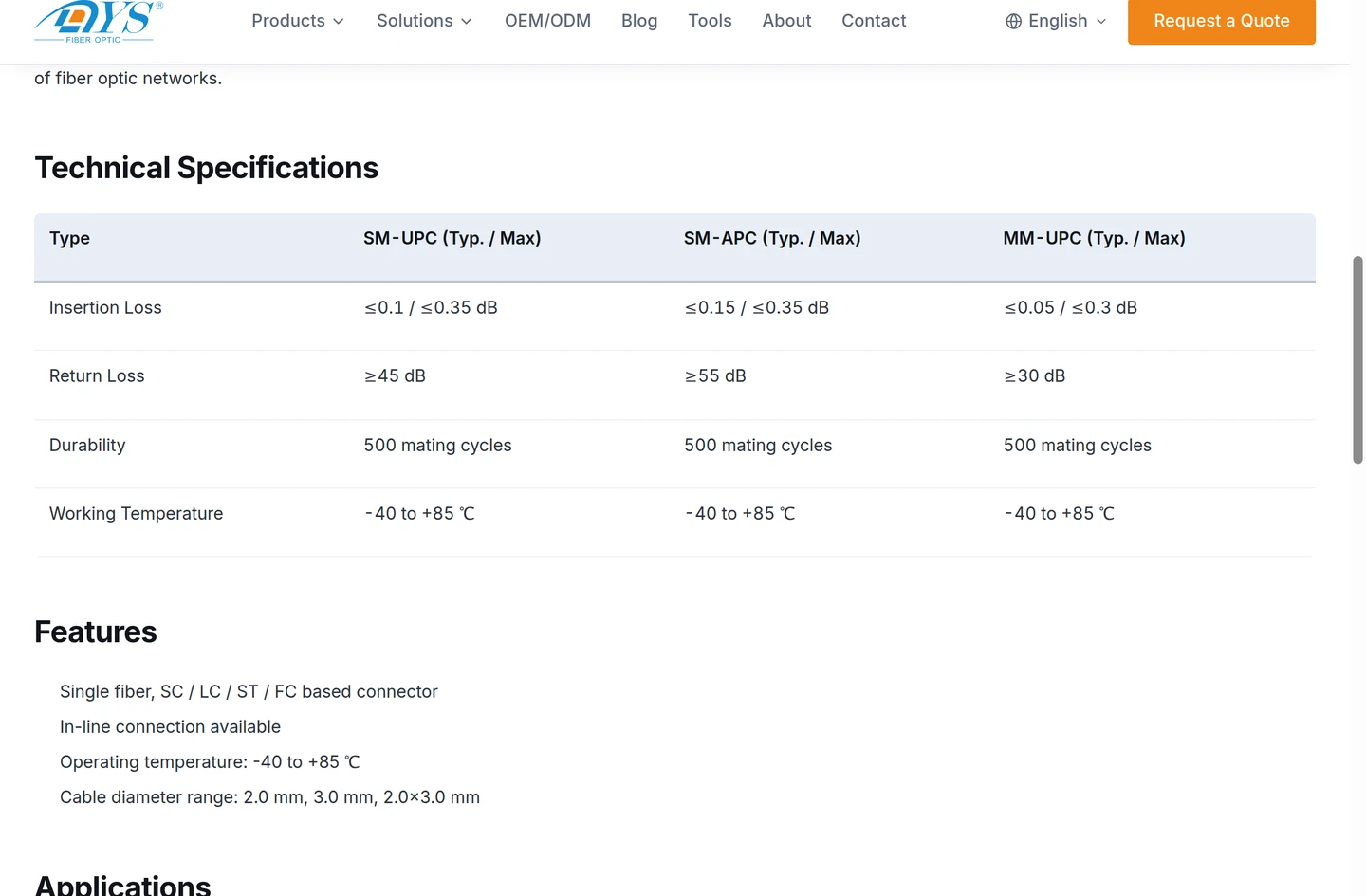
What the re-terminate option publishes: a field-installable connector rated at 500 mating cycles, with a typical and a maximum insertion loss per polish grade — the maximum is the number your acceptance test has to be written against.
Step 4 — Splice and Re-Seal the Span
The splice itself is a procedure with its own discipline — how to splice fiber optic cable walks through stripping, cleaning and cleaving, and the sequence matters more than the speed. What follows here is the part that surrounds it, because the splice is the part most likely to be done well.
Use tools that leave the surfaces intact, and treat cleanliness as part of the repair. The stripping tool has to take the coating off down to the cladding without nicking it, and a precision cleaver has to leave a square end inside the splicer's tolerance — a poor cleave is the usual reason a splice is rejected and has to be re-cut. Clean the stripped fiber with lint-free wipes and the grade of isopropyl alcohol your process specifies, re-clean an endface before you mate it as well as before you fuse it, and never handle a cleaned end with bare fingers. Contamination is the one failure in this whole procedure that costs nothing to prevent and a repeat truck roll to fix. None of it is a substitute for competence either: fusion splicing is a trained operator skill, closures are opened and fibers are spliced by qualified personnel only, and the technician who signs the test record is accountable for the number on it.
Cut back past the damage. Damage to glass does not stop at the visible point of impact. Remove enough cable on both sides that you are certain you are splicing undamaged fiber, and check the cleaved ends for cracks before you fuse them.
Protect the joint before you close anything. A fusion splice gets a splice protector; the protector goes into a tray; the tray goes into the closure with the bend radius respected. Rough handling of a tray is a common way to break a fiber you just spliced successfully — the limits are worth a look at the bend radius rules before you pack a closure.
Restore the cable, not just the glass. This is where a proper restoration diverges from the DIY answer:
- Strength member. The aramid yarn or the steel tape that carried the tensile load has been cut too. Terminate and secure it so the splice does not become the load path.
- Jacket and sealing. The joint needs a closure rated for the environment it sits in. In a manhole or a handhole, that means water. Water-blocking tape or gel, proper sealing, and a fiber optic splice closure whose ingress protection suits the site — and an ingress-protection rating is a smaller claim than it sounds. The digits after IP are not one test: numeral 7 is an immersion test whose conditions the standard itself defines, and numeral 8 is continuous immersion at a depth and duration agreed between manufacturer and user (IEC 60529). Neither covers UV, vibration or repeated re-entry. "IP68" alone therefore tells you very little about a joint in a flooded handhole; the meaningful form is the parenthetical condition behind it — "IP68 (1 m, 1 h)" rather than "IP68".
- Support and routing. A restored span has to be re-supported at the same intervals, and re-lashed on aerial plant, or the joint carries mechanical load it was never designed for.
A joint that is spliced correctly and sealed badly will pass its acceptance test on the day and fail within a season. That failure mode is almost invisible in the SERP's step lists, and it is the one that generates repeat truck rolls.
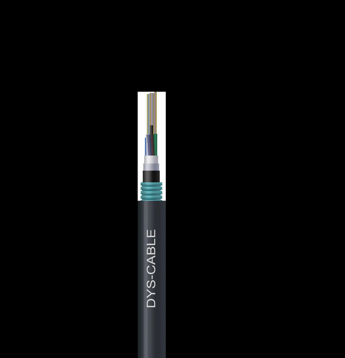
Everything visible here has to be restored, not just the fibers: jacket, steel tape, water-blocking layers and the tube containing the glass.
Step 5 — Test the Repair Against the Link Budget
"Does it light up" is not an acceptance test. A repaired span has to be shown to be inside the loss the link was designed to tolerate, and the evidence has to survive the crew going home.
The splice, on its own. Measure the splice loss rather than inferring it from a successful fusion. A fusion splicer's own estimate is an estimate; the number that matters is what the test set says about the mated, protected joint.
The span, end to end. Take a fresh OTDR trace and compare it with the trace from before the cut — or with the as-built trace from installation. That comparison is what shows you a splice that is acceptable on its own but sits next to a bend or a crushed section that will fail later. Trace from both directions: a splice can read asymmetrically, and the average of two directions is the honest number.
The endfaces. Endface condition belongs in the record, and the inspection is defined by an international standard: IEC 61300-3-35 sets out how debris, scratches and defects are observed and classified. It is an inspection standard, not a loss measurement — a clean endface photograph proves the weakest half of the evidence, and it does not replace the attenuation and return-loss figures.
Against the link budget, not against a feeling. Add the repair's contribution to the rest of the passive loss and check the total against the equipment budget and the engineering reserve. Run the numbers rather than estimating them, and keep the ledger with the job record so the next engineer can see what the span is worth now.
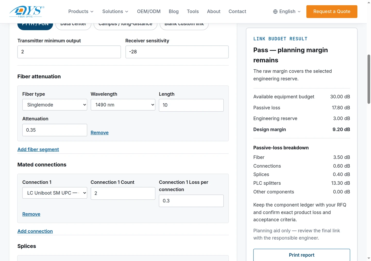
A repair is a line item in the link budget — the ledger above carries splices as their own line, next to fiber, connections and splitters.
Then write it down. Update the cable records with the new splice, the new closure, the new test data, and — this is the one that gets skipped — which fibers are no longer serviceable. A cable that lost two fibers to a dig-in has a different spare capacity than it did yesterday, and nobody will remember that next year unless the as-built says so. Records are also what make the next restoration faster: up-to-date documentation is the single most valuable thing a network can have going into an outage, as the FOA guide named above puts it.
The Cable Construction Decides Whether the Repair Holds
Two cables of the same fiber count can behave completely differently after a cut, and the reason is the construction rather than the glass.
- Loose-tube OSP cable carries bare fibers inside water-blocked tubes around a central strength member, usually with corrugated steel tape and an outer jacket. It tolerates handling, it splices predictably, and its tubes must be re-sealed because water travels inside a tube along the whole span.
- Tight-buffered indoor/outdoor cable has 900 µm or 2.0 mm buffered fibers that are handled directly. It is easier to work in a premises closure and less tolerant of crush and moisture.
- Flat drop cable — the last-mile workhorse, an FRP or steel strength member either side of one or two fibers in a flat jacket — behaves like neither. It is cheap and quick to re-pull, and the correct call on a cut drop is often replacement or re-termination rather than a closure splice at all.
- Armor changes the repair. Corrugated steel tape and an inner jacket add crush and rodent resistance, and they add two more layers to restore at the joint.
Whether a buried span is direct-buried or in conduit, how deep it went in, and whether it is aerial or duct, is decided at installation and paid for at restoration. Where a route sits in that trade-off is set out in underground direct bury versus conduit. The practical rule for a repair is simpler: match what you are splicing into. Fiber type and category matter for loss, and a replacement section of the wrong cable construction changes the mechanical and moisture behavior of the span even when the optical test passes.
What a repair is being asked to withstand is defined, like any other passive optical component, against a set of test and severity categories — IEC 61753-1 is where those categories for passive fiber optic components are set out. For single-mode spans, the fiber and cable characteristics a replacement section has to match are specified in ITU-T G.652.
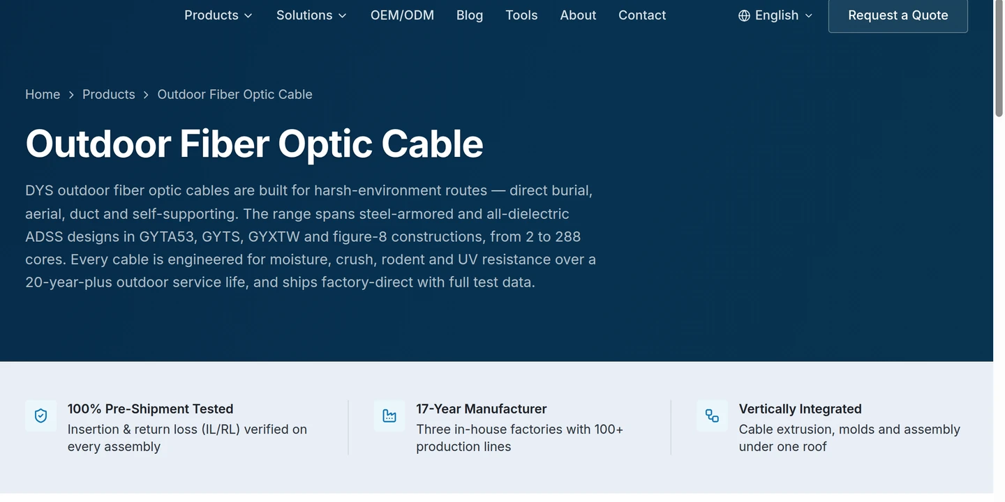
The constructions this section describes, from the supply side: direct-burial, aerial, duct and self-supporting designs, steel-armored and all-dielectric, from 2 to 288 cores — which is why a replacement section has to be matched to the cable already in the ground rather than to whatever is nearest.
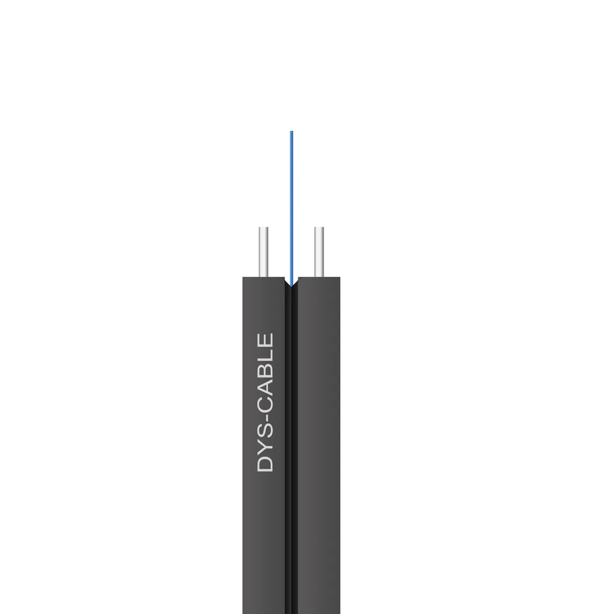
Flat drop cable is the shape a technician is most likely to be holding — one or two fibers between strength members in a flat jacket, cheap to re-pull and quick to re-terminate.
Temporary Restoration: Service Tonight, Permanent Later
Getting the link up tonight and re-splicing properly next week is a legitimate strategy, and pretending otherwise is how crews make permanent decisions under time pressure.
Temporary restoration means restoring enough capacity for the traffic that matters, not restoring the cable. Common forms: mechanical splices on a few fibers, a short replacement section joined with whatever method is fastest, or a switch to spare fibers where the cable has them. What it does not license is leaving the joint unprotected. If it is exposed, seal or enclose it. If a temporary joint is carrying mechanical load, re-support it. If it is in an enclosure that will fill with water, get it out of the water or accept that the temporary repair may last days.
Temporary and permanent differ in two other ways worth writing into the job record: a temporary joint has a lower optical margin (mechanical splices typically add more loss than fusion splices), and a temporary repair has a design life measured in weeks. Set the permanent window before the crew leaves the site, and put the leftover risk — the fibers still out, the joint still exposed — in front of whoever owns the network.
What to Keep on the Shelf So the Next Cut Is Cheaper
Restoration cost is mostly decided before the incident. Five things move the needle.
A fiber optic cable repair kit, stocked and located. Tools and supplies for splicing and termination, spare cable of the right construction and fiber type, spare closures with room for the cable's full fiber count, spare patchcords, splice protectors and trays, cleaning supplies, and connectors — plus a copy of the cable documentation, in a marked box that the people who will need it can find at 2 a.m. The FOA guide named above is the reference to follow on what belongs in it.
Spare fibers. Fiber is the cheapest part of a cable and the most expensive part of a restoration. Cable installed with spare fibers can frequently be restored by switching fibers instead of splicing them.
Service loops. Extra cable stored along the route is what makes a single-closure repair possible instead of a two-closure one. It costs almost nothing at installation and it pays back on the first dig-in.
Route protection, and the locate system. Depth, marker tape, conduit, and registering the route with the local one-call system — in the US, 811 "call before you dig" — are how a network reduces the frequency of the incident in the first place rather than the cost of it. Buried depth and protection practice is covered in how deep is fiber optic cable buried.
On the process side, a locate ticket before third-party excavation is also the evidence trail for damage recovery: a dig-in with no ticket is a different conversation than one with a ticket. The NECA/FOA 301 installation standard is the reference most installations are measured against.
Repair hardware on the shelf, sized to the network. The hardware that turns a restoration from "when the truck arrives with the right parts" into "now" is the boring inventory: outdoor cable in the constructions your routes use, FTTH drop jumpers and drop cable for the last mile, fast connectors for field termination, PLC splitters, terminal boxes and closures. DYS Fiber Optic manufactures that range — FTTH cabling and field-installable connectors and the buried and aerial cable range — across three factories (Huizhou, Mianyang and Vietnam) with published daily capacity of 800 km of optical cable, 30,000 quick connectors and 5,000 FTTX waterproof assemblies per day. If the constraint is stocking a kit for a specific span, ask for the cable construction, the connector interface and the test report together rather than for a catalog: the specification for the repair is the specification of the span.
Safety and Handling on a Restoration Job
The safety content of most repair guides is "wear eye protection", and restoration is the one moment in the life of a fiber network when that advice is testing the wrong thing.
The light in the fiber is not the risk you can see. Transmission systems run in the infrared. A fiber carrying live traffic looks exactly like a dark one, and viewing an unterminated or broken end with the naked eye can cause permanent retinal damage — this is a documented occupational hazard, and OSHA's own guidance on laser hazards is the reference to cite when someone asks why the procedure is written the way it is. Treat every fiber as live until you have proved otherwise at the transmitter, and never look into an endface or a connector to "see if it is lit". This applies in full to a restoration, because a restoration is when a live path is deliberately opened.
A VFL is a laser too. It is low power and the glow at a break is the point — but it is still a laser coupled into a fiber, and the same rule applies: never look into the fiber end or the connector.
Shards. A cleaved fiber end produces a fragment of glass fine enough to go through skin and to work itself into a hand, and impossible to find later. Manage offcuts deliberately — collect them, do not brush them off a tray onto the floor — and stop work if a shard is lost in an area someone has to kneel in.
Bend radius and tension while working. Handling limits do not relax because you are in a hurry: over-bending a fiber to make it reach the tray is how a successful splice fails a month later. And on aerial plant, the working-at-height rules dominate everything in this page.
FAQ
Can a cut fiber optic cable be repaired? Yes, and in outside plant it is repairable to essentially its design condition: a fusion splice with the joint re-sealed in a closure, in the same construction as the original cable. The glass is the easy part. What decides whether the repair lasts is whether the jacket, strength member, water-blocking and support were restored with it — and whether your test data shows the span back inside its loss budget.
How long does a restoration take? It depends far more on locating the fault and preparing the site than on the splice, which takes minutes. The long items are route patrol and excavation on buried plant, working at height on aerial plant, and getting access to a manhole. If you have spare fibers and a service loop, an emergency restoration can be quick; if the damaged ends are too short and the cable needs a new section, you are looking at two closures and a longer window.
Fusion or mechanical splicing for a repair? Fusion for outside plant and for anything intended to be permanent: lower loss, a more reliable joint, and the same joint type the installation used. Mechanical splices are legitimate on premises cable and as a temporary measure to get service back — measure the loss either way and put what you measured in the record.
Is a temporary repair acceptable? As a decision, yes; as a resting place, no. Restoring enough fibers to carry the traffic tonight, protecting the joint and scheduling the permanent splice is a professional call. Leaving an unprotected temporary joint in a handhole and calling the incident closed is how the second failure gets booked against the same cable.
If the next cut is going to be restored from a shelf rather than a supplier's lead time, the specification you need is the specification of the span: cable construction, fiber type, connector interface, and the test data that proves the parts match it. DYS Fiber Optic builds that range — outdoor and indoor/outdoor cable, FTTH drop cable, drop jumpers, field-installable connectors, closures and splitters — in ISO 9001, ISO 14001, ISO 45001, TL 9000, UL, CPR, RoHS, REACH and Anatel certified production, with flexible MOQs for a kit-sized order as well as a rollout. Send the span's details and the kit you are trying to stock, and we will come back with the construction, the interface and the test report behind it.
Basis of this page: the procedure above follows the Fiber Optic Association's restoration and installation guidance and the IEC and ITU standards named inline. No customer installation is used as a worked example, so where a field figure appears, its source is named at the point it is used.