

Installation
How to Test Fiber Optic Cable: OTDR, OLTS, Power Meter
How to Test Fiber Optic Cable: The 5-Step Field Sequence
Knowing how to test fiber optic cable is what separates an installation that passes acceptance from one that fails six months later at the worst possible moment. The good news: the process is not a mystery. Every competent fiber optic cable testing procedure, from the FOA's fiber optic testing reference to the test methods in the TIA and IEC standards, follows the same five-step sequence:
- Inspect and clean every connector end-face before anything touches it.
- Verify continuity and polarity with a visual fault locator or fiber tracer.
- Measure insertion loss end-to-end with a light source and power meter (or an OLTS).
- Run an OTDR trace to locate individual splice and connector events — especially on outside-plant links.
- Compare results against the loss budget, record them, and make the pass/fail call.
That sequence is the whole job. What most field guides leave out is the part you actually need on site: the numbers. What loss is acceptable? What does a dirty connector do to your readings? How do you judge an OTDR trace? This guide answers those questions with the values we use in our own factory every day, and it works for any cable plant — a 10-meter patch cord, a 400-meter FTTH drop, or a 20-kilometer backbone run.
Test when the work is done: after installation, after every splice closure is closed, and whenever a link misbehaves. Incoming cable on a reel? Test that too — a damaged drum from shipping is cheaper to catch before you pull it than after. If you are new to the wider topic, our fiber optic installation, splicing, and testing handbook walks through the full install-and-verify cycle this sequence belongs to.
The Test Kit: What You Need Before You Start
You cannot run a fiber optic test procedure with a voltmeter and a prayer. Light in a fiber is measured with optical instruments, and each one answers a different question. Here is the standard kit, roughly from cheapest to most expensive:
Tool | What it does | Typical price range |
|---|---|---|
Visual fault locator (VFL) | Shines visible red laser light into a fiber to find breaks, tight bends, and bad splices | $30–100 |
Inspection microscope | Magnifies a connector end-face so you can see dirt, scratches, and polish defects | $100–600 (USB video scopes from ~$50) |
Power meter + light source (LSPM) | Measures optical power and insertion loss — the core acceptance test | $200–1,000 for a complete kit |
Optical loss test set (OLTS) | A light source and power meter in one unit, often with automatic loss testing | $500–2,500 |
Optical time-domain reflectometer (OTDR) | Sends pulses down the fiber and maps loss events along its length | $2,000–15,000+ (used units far less) |
Fiber identifier | Clamps onto a live fiber and detects signal presence and direction without breaking the link | $300–1,000 |
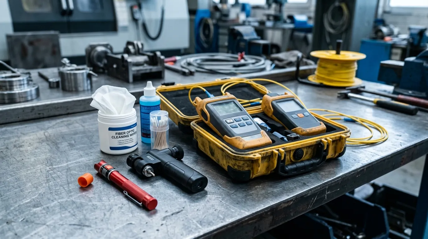
A complete field test kit: power meter and light source, VFL, inspection scope, and cleaning gear.
Two items that do not show up on every shopping list but should: cleaning materials (lint-free wipes, ferrule cleaners, or cleaning cassettes — a few dollars that save hours) and reference test cords that match the connectors you are testing. The VIAVI fiber testing learning center is a good place to see these tools explained by one of the instrument makers.
A few buying notes. If you only maintain short indoor links, a VFL plus a power meter and light source covers 90% of your work. If you pull outside-plant cable with splices, budget for an OTDR or rent one per project — that is the only tool that sees individual splices. Whatever you buy, get it calibrated and check the calibration annually; an uncalibrated meter turns every reading into a guess. And for any test that will be used for acceptance, the reference cords matter more than the meter: the loss of the launch and receive cords is included in your measurement, so cheap cords mean wrong numbers.
Step 1: Inspect and Clean Every Connector First
Dirt is the number one cause of failed fiber optic tests, and it is almost always the cause of a mystery reading. A single speck of dust on a connector end-face can add 0.5–1.0 dB of loss — enough to fail an otherwise perfect link — and it will pass it right back to the next technician who plugs in. That is why the first rule of fiber optic cable testing is inspect, clean, inspect again, on every connector, every time, including your reference cords.
Use a fiber inspection microscope (100–200× video scope is the field standard) to look at each end-face before mating anything. You are checking for three things: contamination (dust, oil, residue), damage (scratches, chips, cracks in the ferrule), and polish defects (an end-face that is not smooth or is recessed — a condition called under-polish). What each polish grade should look like is worth knowing before you judge a connector: our guide to fiber optic connector types and polish grades shows the difference between UPC and APC end-faces and what a healthy one looks like under the scope. If the end-face is dirty, clean it with a dry cleaning method first: a one-click ferrule cleaner or lint-free wipe. If that does not clear it, follow with a wet clean using 99% isopropyl alcohol on lint-free wipes, then dry it and inspect again. Repeat until the end-face is clean.
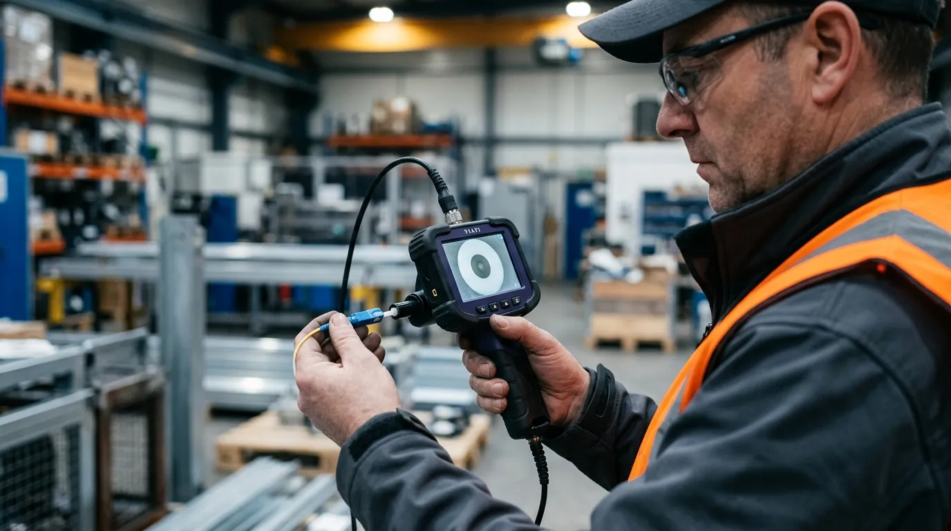
End-face inspection before every test: one dirty connector will fail a link that is otherwise within budget.
Two habits that will save you real time. First, put dust caps back on every connector the moment you unplug it — including on the reel, the patch panel, and your reference cords. Second, never "test through" a connector you have not inspected: the reading will include whatever the dirt contributed, and you will chase a fault that is sitting right in front of you. If your link passes after cleaning, the cable was fine and the connector was not.
Field safety rule: never look directly into a fiber end, a connector ferrule, or an adapter port. Test sources and VFLs are generally low-power, but inspection microscopes focus light into your eye, and some transmission systems are powerful enough to cause injury. When in doubt, measure first with a power meter, then look.
Step 2: Run Continuity and Polarity Checks
Before you measure loss, prove the light actually gets from one end to the other — and through the right fibers. This is the fiber optic continuity test, and the cheapest tool for it is the visual fault locator: a pen-sized device that launches a visible red laser into the fiber. Point it at one end, and you can see the light at the other end through the connector, or even through the jacket of many yellow/ orange simplex cables. No light at the far end means a break, a bad splice, or a tight bend somewhere in between; walk the cable and the red glow will usually show you exactly where it leaks.
The VFL is also your low-budget answer to "how to test fiber optic cable without a tester": for short runs, continuity checking with a VFL plus a fiber optic light test using a flashlight and your phone camera at the other end will confirm the path — it will not give you a loss number, but it tells you the fiber is not broken. On a budget, that is a legitimate first pass, not a substitute for loss testing on links that matter.
Continuity and polarity go together. On a duplex link or a multi-fiber cable, the fiber that is "lit" at the far end must be the fiber your equipment expects. Use the VFL or tracer to confirm polarity on every pair — one fiber transmitting to the correct receiver, one receiving from the correct transmitter. A crossed pair is invisible to a loss test (loss will look fine) and will only show up as a link that never comes up. If the fiber path checks out but the link still will not come up, a loopback plug on each end isolates whether the problem is the fiber or the transceiver. If you are troubleshooting, also check for the classic failure modes: a dark far end (break or bad splice), light that flickers (a marginal connector), and high loss with no visible fault (dirty end-face or a macro-bend — a bend tighter than the cable's minimum bend radius, which you will usually find at a patch panel or in a poorly managed tray).
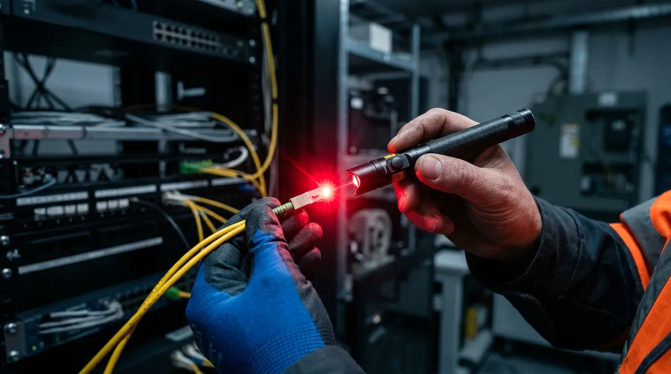
A VFL continuity check confirms the fiber is unbroken before you invest time in loss testing.
Remember the VFL is a visible laser — do not stare into the output end, and when tracing fibers in a splice tray, look at the fiber from the side rather than down its end.
Step 3: Measure Insertion Loss with a Light Source and Power Meter (OLTS)
Continuity proves the fiber is intact. Insertion loss proves it is good enough — and this is the measurement every acceptance standard is built around. The fiber optic power meter test works like this: a calibrated light source launches a known power into one end, a power meter measures what arrives at the other end, and the difference in decibels is the loss of the link. The instrument pair is called an LSPM (light source and power meter); the integrated version is the optical loss test set (OLTS), and either one runs the same procedure.
The step that separates good measurements from garbage is setting the reference — the "0 dB" point. You do not measure absolute power; you measure loss relative to a reference established through your test cords:
- Clean and inspect your reference cords and the source and meter ports.
- Connect the source to the meter through your reference cords and mating adapters.
- Let the source stabilize (a few minutes for laser sources), set the meter to the test wavelength, and zero the reading.
- Insert the cable under test between the cords — the meter now shows only the loss added by the link.
How many reference cords you use determines what your number includes. The one-cord method (reference through the launch cord only) includes both end connections of the link and is the preferred, lowest-uncertainty method for permanent links. The two-cord method includes one end connection. The three-cord method excludes both end connections. Standards differ on which to use where — the details are well summarized in Fluke Networks' Demystifying Fiber Test Methods — but the practical rule is: pick the method the contract specifies, and say in your report which one you used, because the same physical link can read 0.5 dB apart between methods.
Two units trip everyone up at first. dB measures loss — a ratio, always relative, always a comparison to your reference. dBm measures absolute power (decibels relative to a milliwatt). Your meter reads dBm during the reference step and dB during the loss step. And the more negative a dBm reading, the less power is arriving: −20 dBm is a stronger signal than −25 dBm.
Test at the wavelength the link will actually carry. Multimode fiber is tested at 850 nm (and optionally 1300 nm) with LED sources; singlemode at 1310 nm (and optionally 1550 nm) with laser sources. Use a mandrel wrap on multimode launch conditions when your test kit includes one — it strips out the higher-order modes that would otherwise flatter the reading.
What counts as a good number? Industry expectations for the components in your link:
Component | Typical loss | Planning value |
|---|---|---|
Singlemode fiber | 0.35–0.40 dB/km @ 1310 nm; 0.20–0.25 dB/km @ 1550 nm | use 0.4 dB/km |
Multimode fiber | ~3.5 dB/km @ 850 nm; ~1.5 dB/km @ 1300 nm | use 3.5 dB/km |
Mated connector pair | 0.1–0.5 dB (well-polished LC/SC) | plan 0.5 dB (SM), 0.75 dB (MM) |
Fusion splice | 0.02–0.1 dB typical; investigate above 0.3 dB | plan 0.15 dB |
Mechanical splice | 0.2–0.5 dB | plan 0.5 dB |
Field rule: if the measured insertion loss comes in above budget, do not re-test the whole link yet — clean and re-inspect every connection first (Step 1), then re-run. Dirty connectors account for more failed acceptance tests than bad splices and bad cable combined.
For context on how loss budgets behave at high speed, our 400G/800G data center cabling guide shows how these same numbers scale in MPO-based fabrics.
Step 4: Pinpoint Faults with an OTDR
The light source and power meter tell you that the link loses too much. The OTDR tells you where. An optical time-domain reflectometer fires short pulses into the fiber and watches the light that scatters back; because the return signal arrives over time, the instrument can map loss against distance. That makes OTDR testing the standard tool for outside-plant links with splices, and for troubleshooting when a link fails and you have no idea which segment is at fault. (For the physics behind it, the OTDR working-principle article on Wikipedia is a clean primer.)
Learning how to use an OTDR is mostly learning to set it up honestly:
- Connect a launch cable between the OTDR port and the link under test — at least 100–150 m of the same fiber type. Without it, the connector at your end sits inside the OTDR's near-end dead zone and you cannot measure its loss.
- Set the index of refraction for the fiber type (printed on the reel or datasheet; 1.4682 is a common singlemode value) — this is what converts time into distance.
- Set the wavelength to match the link (1310 nm for loss events, 1550 nm for bend-sensitive inspection on long singlemode runs). On multimode plant, the fiber grade changes what you should expect from the numbers — our OM1–OM5 fiber grades compared guide covers the differences.
- Choose pulse width and range: a longer pulse reaches farther but hides short spans; start with the range that covers the link plus launch and receive cables.
- Average the trace (the OTDR does this automatically) until the noise floor flattens, then read the events.
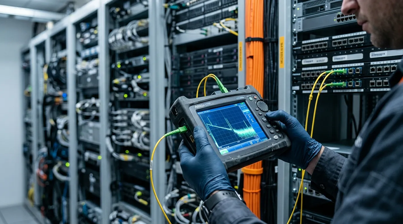
An OTDR trace turns distance into x-axis and loss into y-axis — each step down is a splice or connector.
Read the trace as a series of steps: a clean downward step is a splice or connection (the drop in the trace is its loss); a spike upward is a reflective event (typically a connector or mechanical splice — strong reflection peaks mean poor return loss, a sign of an under-polished or contaminated end-face); a sudden cliff is a break or a macrobend leaking light. The numbers you care about: splice loss should sit around 0.02–0.1 dB for fusion splices — anything over about 0.3 dB is worth redoing on an outside-plant link, and over 0.5 dB on a mechanical splice means it was assembled badly. Connector events of 0.5 dB or less are normal; large reflective spikes at the far end are just the end of the fiber. Pay attention to the total span loss the OTDR reports at your test wavelength — it should agree with your power-meter measurement within about 0.1–0.2 dB. If the two disagree, suspect the launch setup or a reference error, not the cable.
For multi-fiber and MPO/MTP work, remember that an OTDR tests one fiber at a time; a 12-fiber MPO trunk needs twelve traces (or a fanout kit). Test every fiber, not a sample, on links that must pass acceptance — and keep in mind that the loss numbers that matter in high-density data centers are set by the same budgets we use in Step 5, applied per fiber.
Step 5: Compare Results Against the Loss Budget (and Record Them)
A loss reading means nothing until you compare it to the link's loss budget — the maximum loss you can accept, calculated before you ever pick up a meter. The formula is simple:
Loss budget = (fiber attenuation × length) + (connector loss × number of mated pairs) + (splice loss × number of splices)
Worked example — a 10 km singlemode backbone with two splices and four mated connector pairs:
Budget item | Value | Loss |
|---|---|---|
Fiber: 10 km × 0.4 dB/km @ 1310 nm | 4.0 dB | 4.0 dB |
Connectors: 4 mated pairs × 0.5 dB | 2.0 dB | 2.0 dB |
Splices: 2 × 0.15 dB | 0.3 dB | 0.3 dB |
Total budget | 6.3 dB |
If your measured insertion loss is ≤ 6.3 dB, the link passes. If it is close to the budget, or your OTDR shows one event eating a disproportionate share, fix that event and re-test rather than accepting a marginal pass — margins shrink as links age, and a 0.2 dB splice does not get better with time.
Which standard governs depends on where you are and what you installed. North American structured cabling follows TIA-568.3-D, with the loss test methods in TIA-526-14-C (multimode) and TIA-526-7 (singlemode) — adoptions of IEC 61280-4-1 and IEC 61280-4-2. The international equivalent for link testing is ISO/IEC 14763-3. All of them share the same shape: measure at the operating wavelength, against a documented reference method, and compare to a pre-calculated budget. The FOA's loss budget guide walks through budget math for both multimode and singlemode plants if you want a second worked example.
Then write it down. A test with no record is a test that never happened: record the date, the fiber IDs, the test method (one/two/three-cord), the wavelengths, the reference value, the measured loss per fiber, and the OTDR traces. Keep the file with the as-built drawings. When a link degrades next year, that record is the baseline you compare against — and on customer-accepted jobs, it is your proof of compliance. This is also the fiber optic test procedure auditors and certification bodies will ask for, so make it a habit rather than an afterthought.
What DYS Tests Before Your Cable Ships
Every step in this guide applies just as much on our production floor as on your job site. At DYS Fiber Optic, every cable reel is tested before it leaves the factory — 100% pre-shipment testing under our ISO 9001 and TL 9000 quality systems, with an in-house reliability lab running mechanical and environmental tests (tensile, bending, torsion, waterproofing, and more) across 12+ test stations. Connector and patch-cord production is tested to GR-326, the telecom industry's connector reliability standard. So when a spool of GYTA53 shows up on your truck, the continuity, loss, and dimensional numbers behind it are already on file — and we will share them.
That is the practical takeaway for buyers: when you are sourcing cable, ask the manufacturer what they test and whether you can have the test data. A supplier that cannot produce per-reel test records is asking you to be their quality department. If you want to see what our factory test reports look like, or you are specifying a cable and need the attenuation and test data for your loss budget, contact our engineering team — we answer with numbers, not adjectives.
FAQ: Quick Answers for the Field
How much does a fiber tester cost? A usable kit starts around $200–300: a VFL ($30–100) plus a power meter and light source ($200–1,000). An OLTS runs $500–2,500, and an OTDR is typically $2,000–15,000+ new. Rent an OTDR for one-off outside-plant jobs.
How do you test fiber optic cable without a tester? For continuity only: use a VFL (a flashlight-grade visible laser pen) at one end and watch for light at the other; a phone camera helps see faint red light. This proves the fiber is unbroken but gives no loss number — treat it as a first pass, not acceptance.
How can I tell if a fiber optic cable is bad? Symptoms: no light at the far end (break or bad splice), a VFL glow leaking through the jacket (break or macrobend), high loss on the power-meter test with no obvious event (dirty connectors first, then bends), and an OTDR trace with a steep event where none should be.
How often should fiber optic cable testing be done? At minimum: on incoming reels, after installation or any splice closure, and whenever a link fails. On critical infrastructure, re-test on a schedule and keep the baselines — degradation between two test dates is the most reliable early warning you have.