

Data Center
400G to 800G Data Center Cabling: Fiber Counts & OM4 vs OS2
400G and 800G data center cabling is the physical layer of the current AI-scale network buildout: the MPO/MTP trunk assemblies, fiber cassettes, patch panels, and polarity-managed connectivity that carry 800G SR8 and DR8 links between spine and leaf switches. Choosing the right fiber count, fiber type, and connector grade now determines whether your next upgrade is a transceiver swap or a full cable re-pull.
Key takeaways
- Fiber count follows the transceiver's lane structure. A 400G SR4/DR4 link needs 8 fibers (MPO-8); an 800G SR8/DR8 link needs 16 fibers (MPO-16). 400G FR4/LR4 WDM links run on a duplex pair.
- OM4 vs OS2 is a reach and future-proofing decision, not a preference. Multimode OM4 covers the short intra-rack and leaf-to-leaf reaches where 800G-SR8 lives; single-mode OS2 is the 500 m+ and 1.6T-ready choice.
- Loss budget is the gate that actually fails. Two MPO mated pairs plus patch connections can consume 1.5–2 dB of a ~3 dB 800G channel budget; low-loss connector grades are the difference between passing and failing Tier-1 certification.
- Standards tell you what to build. TIA-942, ANSI/TIA-568.3, and ISO/IEC 11801 govern the cabling plant; IEEE 802.3 defines the optics.
- Migrate on data, not on hope. Polarity, fiber type, and measured loss records decide whether 400G→800G is optics-only, a repatch, or a trunk replacement.
What actually changes when you move from 400G to 800G
The jump from 400G to 800G is not a linear capacity increase; it is a change in lane rate and in how the optics use fiber. 400G Ethernet, defined across the IEEE 802.3bs/cm/cu/db suite (see IEEE 802.3), runs on either four 100G PAM4 lanes (400G-SR4, -DR4, -FR4) or eight 50G PAM4 lanes (400G-SR8). 800G, defined in IEEE 802.3df, standardizes eight 100G PAM4 lanes for parallel multimode and single-mode optics (800G-SR8, 800G-DR8), with 200G-per-lane variants (800G-SR4/DR4) arriving on the roadmap.
Two consequences follow for the cabling layer.
First, the optical module form factor changed but the physical interface still ends in an MPO or duplex connector. 800G transceivers ship in OSFP and QSFP-DD packages. QSFP-DD keeps the 8-fiber MPO-8 heritage of 400G-DR4; OSFP-class 800G-SR8/DR8 modules expose MPO-16. The port counts per rack unit differ, but the connector language — MPO counts, polarity, APC vs UPC — is the same one you already manage at 400G.
Second, power and thermal budgets tightened. A 400G OSFP port runs roughly 12–15 W; an 800G port runs roughly 20–25 W, which is why the Cisco 800G client optics whitepaper frames cabling choices inside a power-per-Gbps analysis. Short-reach DAC and AEC copper still owns the 1–3 m intra-rack zone; active optical cables (AOC) and structured fiber take over from there — and the fiber decision is exactly where most migration budgets are won or lost.
Copper-versus-fiber is not the only split to plan for. The east-west spine-leaf traffic pattern of AI clusters — the NVIDIA GPU pods and hyperscale builds that dominate current data center growth — concentrates traffic in the middle of the network (over InfiniBand NDR fabrics and RoCEv2-over-Ethernet alike), which is where high-density MPO trunking earns its keep. For the full context on where this fits in a data center, start from the Data Center Fiber Cabling Guide — the pillar this article belongs to. A useful industry reference for the structured-cabling view is Corning's 10G–400G structured cabling guide.
There is also a generation gap to plan around. A "400G-ready" cabling plant built two years ago was often terminated with MPO-8 trunks and Type A polarity, sized for 400G-SR4/DR4. An "800G-ready" plant is terminated with MPO-16 trunks and Type B polarity, sized for 800G-SR8/DR8. If your existing plant documentation says MPO-8, that is not a defect — it is a signal that the 800G step will be a Path 2 or Path 3 migration (we cover the paths in detail below), not an optics-only swap. Knowing which generation your plant was built for is the cheapest information you can gather before you start.
How many fibers 400G and 800G really need
The single most common procurement error at 400G and 800G is ordering fiber counts by habit instead of by lane structure. The math is simple: parallel optics uses two fibers per lane (one transmit, one receive), so fiber count = 2 × lanes.
Link | Lanes | Fibers | Connector |
|---|---|---|---|
100G-SR4 (4×25G) | 4 | 8 of 12 | MPO-12 (legacy) |
400G-SR4 / DR4 (4×100G) | 4 | 8 | MPO-8 |
400G-FR4 / LR4 (4×100G WDM) | 1 pair | 2 | Duplex LC |
400G-SR8 (8×50G) | 8 | 16 | MPO-16 |
800G-SR8 / DR8 (8×100G) | 8 | 16 | MPO-16 |
800G-FR4 / LR4 (4×200G WDM) | 1 pair | 2 | Duplex LC |
1.6T (16×100G, roadmap) | 16 | 32 | MPO-32 |
The duplex-vs-parallel distinction is where the "how many fibers" question gets answered: WDM optics (FR4/LR4) multiplex wavelengths onto one fiber pair, so a 400G or 800G link needs just two fibers and a duplex LC — at the price of laser cost and power. Parallel optics (SR/DR) keep the lasers simpler and cheaper per lane but multiply fiber usage — which is why the high-density MPO ecosystem exists in the first place.
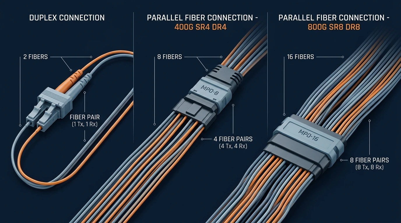
Figure: the fiber-count math in one picture — duplex WDM on 2 fibers, 400G SR4/DR4 on 8, 800G SR8/DR8 on 16.
Two planning rules come out of this table:
- Size trunks for the largest lane count you will run, not today's. If a 400G-SR8 or 800G-SR8 upgrade is plausible in the trunk's life, spec MPO-16 (16 fibers) now. An MPO-16 trunk carries 800G-SR8 and 2×400G today, and a 1.6T future.
- Match breakouts to the equipment end. The MPO side terminates in cassettes or fanouts to LC duplex for switch ports; the fiber-count math on the equipment side is set by the transceiver, not by preference.
A concrete example makes the math tangible. A leaf switch with a 400G-SR8 uplink needs 16 fibers; if the trunk is a 16-fiber MPO-16 and the switch port accepts 2× MPO-8 breakouts (common on QSFP-DD), the same trunk serves two 400G-SR4 links on the way to 800G. Conversely, an MPO-12 trunk from the 100G era has only 12 fibers — enough for 400G-SR4-style 8-fiber links with four fibers spare, but structurally short of the 16 fibers an 800G-SR8 link needs. That single digit (12 vs 16) is the most common reason an "800G upgrade" becomes a "trunk replacement project".
The full fiber-count range — MPO/MTP trunks from 8 to 144 fibers, cassettes, harnesses, and fanout patch cords — is available from a single manufacturer at the MPO/MTP data center cabling product line.
OM4 vs OS2: matching fiber type to your 400G/800G reach
OM4 vs OS2 is the decision that splits 400G/800G cabling into two completely different cost and upgrade trajectories. The short version: multimode OM4 wins inside the reach envelope; single-mode OS2 wins everywhere else and wins the long game.
Reach requirement | 400G choice | 800G choice |
|---|---|---|
≤ 50–70 m (intra-rack, top-of-rack to leaf) | OM4 (400G-SR4/SR8) | OM4 (800G-SR8, ~50–70 m class per 802.3df) |
≤ 70–100 m (leaf-to-leaf, most spine-leaf) | OM4 (400G-SR4/SR8) | OM4 (800G-SR8, short) or OS2 |
500 m (spine-to-spine, large pods) | OS2 (400G-DR4) | OS2 (800G-DR8) |
2 km / 10 km (campus, inter-building) | OS2 (400G-FR4/LR4) | OS2 (800G-FR4/LR4) |
The reach figures are IEEE 802.3 class limits — the exact numbers vary by 802.3 clause and transceiver vendor, so treat the table as planning input and confirm against the module datasheet. The principle is stable: at 400G, OM4 supports 70–100 m-class SR links and OS2 DR4 reaches 500 m; at 800G, the multimode reach envelope tightens (800G-SR8 on OM4 drops to roughly half the 400G-SR8 distance at the conservative end of the clause range) because 100G PAM4 per lane is harder on modal dispersion. OM5 multimode extends the OM4 envelope at 400G/800G (commonly ~70 m for 800G-SR8) and is worth considering in new short-reach plants; for the full OM1–OM5 comparison, see our OM1–OM5 fiber grades guide.
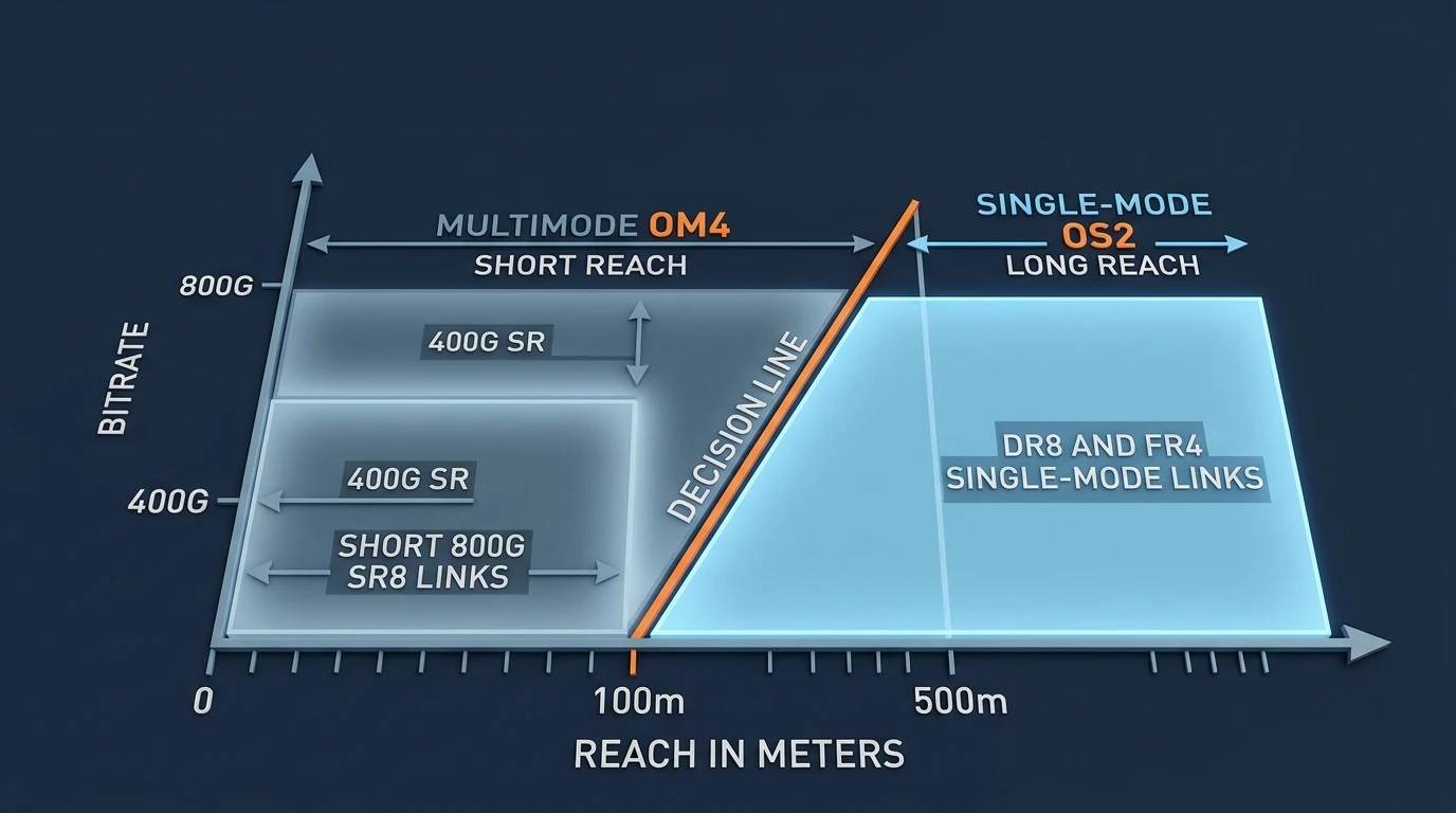
Figure: the OM4 vs OS2 decision boundary — reach class decides the fiber type, and the boundary moves down as lane rates climb.
Three practical signals for the OM4 vs OS2 call:
- Existing plant. If the backbone is already OS2 (the norm for any cable that left the building), stay OS2 — mixing types in a trunk is a re-pull later.
- Transceiver economics. VCSEL-based SR optics are cheaper at 400G; at 800G the price gap to single-mode optics narrows, which quietly removes the cost argument for multimode in new builds.
- 1.6T horizon. The 1.6T roadmap is heavily single-mode (200G/lane and co-packaged optics are OS2 designs). A new OS2 backbone has a materially longer useful life than a new OM4 backbone if your horizon is 2027+.
MPO-8, MPO-16, and the connector map for 400G/800G
Once the fiber type is set, the connector map decides the SKUs. For 400G/800G the working set is small:
- MPO-8 — 400G-SR4/DR4 and 100G PSM4-style 4-pair links.
- MPO-12 — legacy 40G/100G SR4 plant; still common in installed bases, carries 400G only via breakout or with unused fibers.
- MPO-16 — 400G-SR8 and 800G-SR8/DR8, the growth standard for new high-density builds.
- Duplex LC (and CS/SN for 200G/lane) — WDM links and the equipment-side breakout.
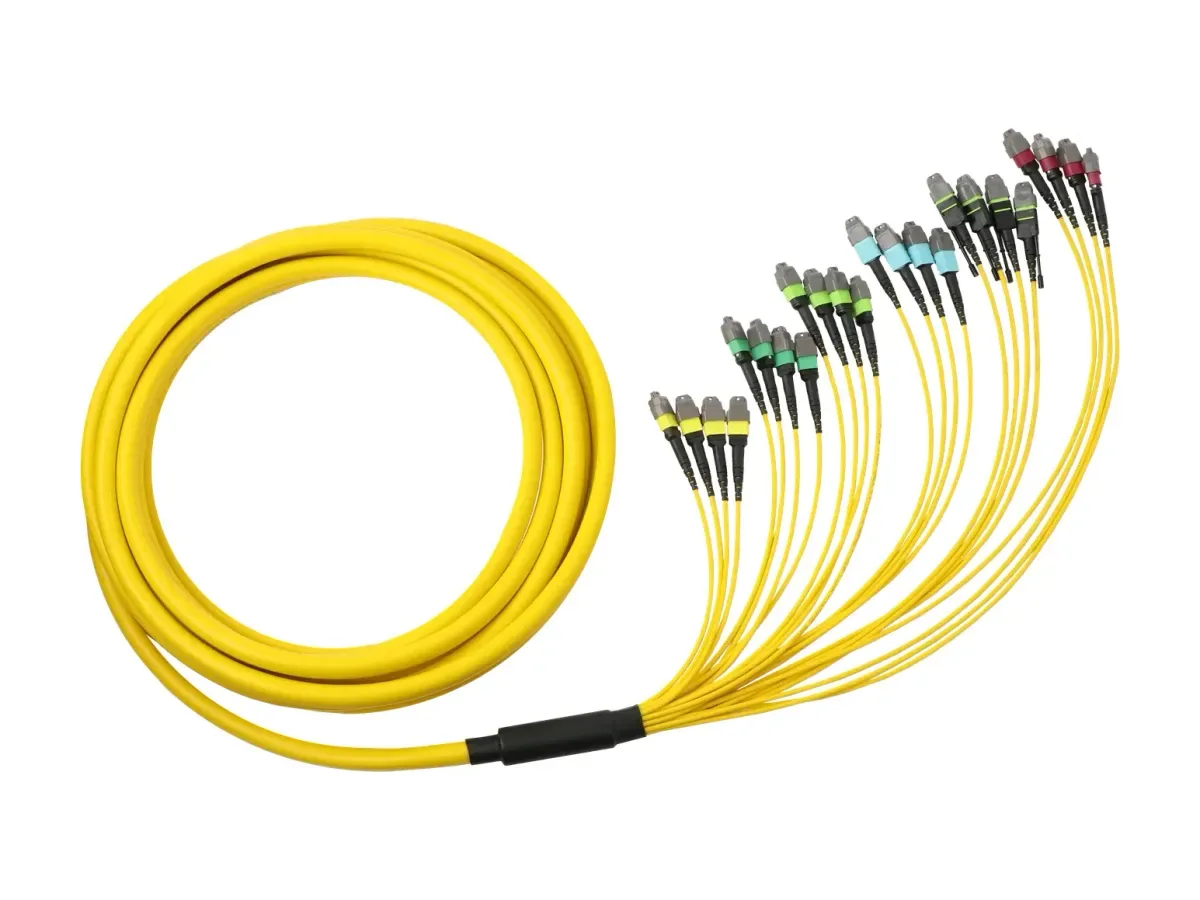
Figure: a real MPO/MTP trunk — the pre-terminated backbone assembly that carries 8, 12, 16 or more fibers between zones.
Three details decide whether this connector map works in the field:
Polarity. TIA-568 defines three polarity methods (Type A, B, C) for MPO systems. 800G-SR8 parallel links overwhelmingly use Type B (straight-through, key-up to key-down), which is what the SERP's own AI Overview now cites as the default for MPO-16 parallel cabling. Whatever method you pick, the trunk, cassettes, and patch cords must be ordered to the same polarity scheme — a polarity mismatch is the classic "cable tests fine, link won't come up" failure.
APC vs UPC. Single-mode MPO systems use APC (angled, 8°) end faces; multimode MPO uses UPC (flat). The two never mate correctly, and an APC-to-UPC connection in an MPO trunk is a silent insertion-loss disaster. Specify the polish on every SKU and put it on the label.
Gender (guide pins). MPO trunks are female (no pins) by convention; the pins live on the patch cords or cassettes. Pin ordering mistakes bend ferrules and damage both connectors — a factory-build and test process catches this before it reaches your rack. This is exactly why pre-terminated, 100% tested assemblies earn their keep: polarity, gender, polish, and insertion loss are verified per assembly before shipment, and every unit ships with IL/RL test data — factory-tested MPO fan-out patch cords are a working example of that process applied to the MPO-to-LC break.
Put the pieces together and the architecture is a chain: switch port → patch cord → cassette (MPO-to-LC) → trunk (MPO-16) → cassette → patch cord → switch port. Each cassette terminates the MPO trunk into the LC duplex ports the equipment actually uses; the trunk carries the fibers untouched across the aisle or between zones. The polarity method must be consistent across every link in that chain — trunk, cassette, and patch cord are ordered as one polarity family, not three independent SKU decisions. Two things keep the chain maintainable: standardized cassettes (so a later 800G-SR8 change is a cassette swap, not a trunk pull), and labeling that records polarity, polish, and fiber count on every assembly. On the horizon, VSFF connectors (MDC, SN, CS) shrink the same math into denser faceplates for 200G/lane optics — the fiber-count and polarity logic carries over unchanged.
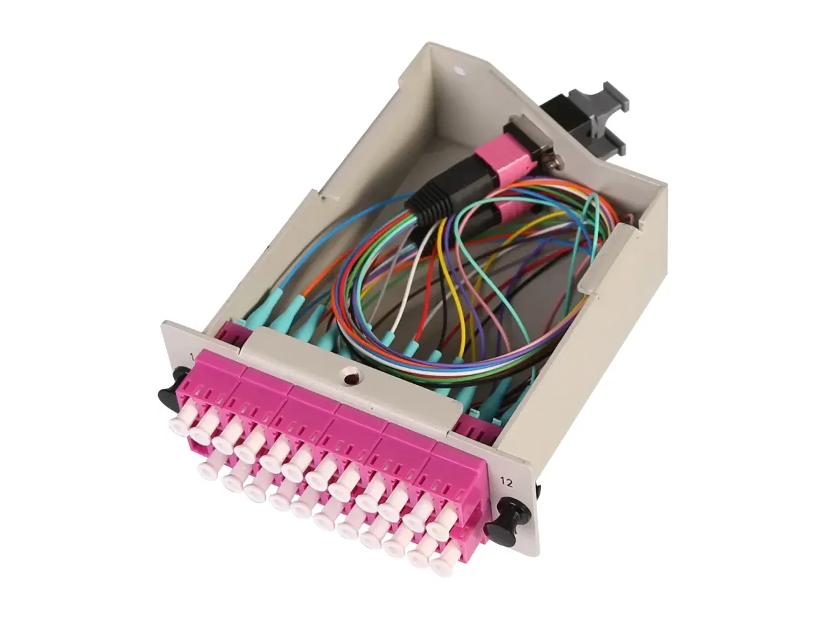
Figure: the cassette is the transition point — MPO trunk on the rear, LC duplex ports on the front, polarity handled inside the module.
Link budget: every dB counts at 400G and 800G
The most under-accounted line item in 400G/800G cabling projects is the channel loss budget. PAM4 modulation leaves far less optical margin than the NRZ links of the 100G era, so the cabling channel — connectors, splices, and cable — must come in under the transceiver's maximum channel insertion loss, typically around 3 dB for 800G-SR8 (verify the exact number on your module's datasheet).
A worked example, using realistic per-component numbers (matching Telcordia GR-326 / GR-1435-grade components):
Component | Standard grade | Elite (low-loss) grade |
|---|---|---|
MPO mated pair (multimode, 12F) | ≤ 0.50 dB | ≤ 0.35 dB |
LC duplex mated pair (multimode) | ≤ 0.20 dB | ≤ 0.10 dB |
Cable loss, 20 m multimode trunk (~3 dB/km @ 850 nm) | ≈ 0.06 dB | ≈ 0.06 dB |
A typical 800G-class cabling channel — MPO trunk with cassette breakouts to LC patch cords at the equipment — has two MPO mated pairs (one at each end of the trunk) plus two LC duplex patch connections: standard grade ≈ 1.46 dB total; Elite grade ≈ 0.96 dB total. Both fit inside a 3 dB budget — but add a third MPO mated pair or a damaged connector, and the standard-grade channel has burned most of its headroom (≈ 2.0 dB with the third pair), leaving little margin for temperature, aging, and contamination. At 800G the difference between "passes" and "barely fails" is routinely one connector pair.
The same arithmetic explains why trunk length is rarely the problem. Multimode attenuation at 850 nm runs roughly 3 dB/km, so even a 100 m trunk contributes ~0.3 dB — the connectors, not the glass, eat the budget. Any migration plan that focuses on cable length while ignoring mated-pair counts has the budget conversation backwards. If the channel already fails Tier-1, the usual culprits, in order: a bad or mismatched connector (check polish and cleanliness first), an extra mated pair, and only then the fiber itself.
Three procurement rules that follow:
- Buy the loss grade the link actually needs. MPO/MTP cassettes and trunk assemblies are available in Standard and Elite grades (Elite MPO mated-pair IL ≤ 0.35 dB, tested per assembly); for 800G-SR8 or long trunk runs, Elite removes budget pressure instead of creating it.
- Demand per-assembly test data. IL/RL per cable with serial-number traceability is what lets you predict channel loss before installation instead of discovering it at Tier-1 certification. Pre-terminated assemblies are the practical vehicle: DYS pre-terminated cables ship 100% factory-tested with GR-326/GR-1435 conformance.
- Budget for re-mating. GR-1435 allows ΔIL ≤ 0.3 dB after 50 MPO matings; every move, add, and change consumes that allowance. Design the channel with headroom, not at the limit.
The standards that govern 400G/800G cabling
If you are asked "what are the major standards for data center cabling?", the answer splits cleanly into plant standards and optics standards:
- TIA-942 — Data Center Infrastructure Standard. Defines data center architecture and the four availability tiers (I–IV). It governs the structured cabling topology (HDA/EDA/ZDA zones) your 400G/800G plant is laid out in, including the MPO backbone between zones.
- ANSI/TIA-568.3 (and its components sections) — the optical fiber cabling component standard: connector types, polarity methods, and performance classes for the MPO/LC components themselves.
- ISO/IEC 11801-1 — Generic Cabling for customer premises, the international counterpart that harmonizes channel classes and component grades across vendors.
- IEEE 802.3 — the Ethernet standard that defines the optics: 802.3bs (200G/400G), 802.3cm (400G over multimode), 802.3df (800G). This is where lane counts, reaches, and channel insertion-loss limits come from. For the jacket and fire-rating half of the compliance story (LSZH vs OFNR vs OFNP, and what the codes require where), our OFNP/OFNR/LSZH fire-ratings guide covers the material choices that keep a high-density trunk plant code-clean.
Migration paths: 400G to 800G without a re-pull
The 400G→800G migration question is really a plant-assessment question. Before ordering anything, answer five questions from your existing documentation:
- Fiber type — is the backbone OM4 or OS2? (If you don't know, a fiber certifier tells you in minutes.)
- Fiber count per trunk — MPO-8, MPO-12, or MPO-16? Counts below 16 fibers cap you below 800G-SR8/DR8 without a re-pull.
- Polarity scheme — Type A, B, or C? It must match the new optics' expectation (typically Type B for parallel 800G).
- Channel loss records — do you have Tier-1 test results from the last certification? No records means you will budget blind.
- Age and bend rating — legacy 62.5/125 or tight-bend-restricted OM3 runs that worked at 10G are the first candidates for replacement.
Then choose the cheapest path that clears the check:
- Path 1 — Optics-only swap. Plant is OS2 or OM4, counts and polarity already match (e.g., 400G-SR8 → 800G-SR8 on the same MPO-16 trunks). Replace transceivers and repatch; re-certify the channel. This is the low-cost, low-risk 80% of upgrades.
- Path 2 — Breakout and repatch. Fiber counts exist but the equipment ends are wrong (e.g., 16-fiber trunks terminated to 2× MPO-8 or LC fanouts). Swap cassettes/harnesses at the panel rather than the trunk — harnesses and high-density patch panels (up to 144 fibers per 1U) are built precisely for this, so new cassettes slot in without touching the backbone.
- Path 3 — Trunk replacement. Fiber type or count blocks the upgrade (OM3 backbone, MPO-12-only plant, or an OS2 requirement for 500 m+ DR8). Pull new OS2 or OM4 pre-terminated MPO trunk cables in the next maintenance window and align the whole zone to Type B polarity.
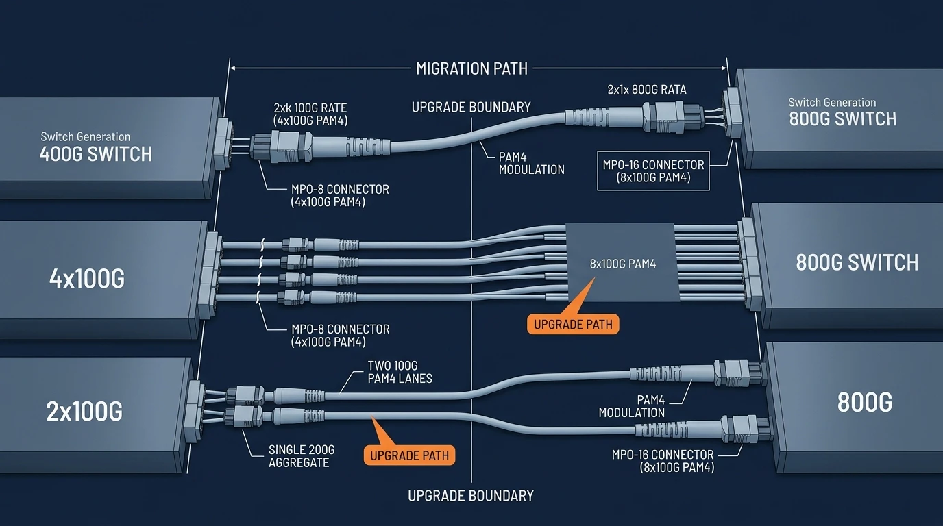
Figure: the migration path — lane structure and connector generation at 400G (MPO-8) and 800G (MPO-16), with the upgrade boundary between them.
The forward look changes the math again: 1.6T Ethernet and co-packaged optics (CPO/LPO) push lane counts to 16 (MPO-32) and shift the cost center from the cable plant to the optics. TCO-conscious buyers are already speccing OS2 backbones and MPO-16+ trunks with the 1.6T roadmap in mind — a decision the parent pillar of this cluster, the Data Center Fiber Cabling Guide, develops further. For the full picture of where high-density cabling fits in a data center solution, see the data center cabling solution page.
Testing and certification before you cut over
No 400G/800G channel is live until it has passed Tier-1 certification, and the testing discipline is part of the cabling decision, not an afterthought:
- Tier-1 testing verifies the channel: insertion loss against the calculated budget and polarity (and length, for copper). Every MPO-16 trunk, cassette breakout, and patch connection in the path is included. Fluke's explainer on Tier-1 vs Tier-2 certification is the standard industry reference.
- Tier-2 testing adds OTDR to locate the fault when a channel fails — which connector or splice is over budget, measured in meters from the launch point. The Fiber Optic Association's testing reference is a solid neutral primer on the techniques.
- Test records are a procurement asset. Certified channels with serial-numbered test data make the next migration (800G → 1.6T) a documentation exercise instead of a re-survey. When you buy pre-terminated assemblies, get the factory IL/RL data at the same time — DYS includes per-assembly test reports, and MPO loopback test cords are the standard tool for verifying transceiver ports during the cutover itself.
Frequently asked questions
What are the major standards for data center cabling? The plant is governed by TIA-942 (data center infrastructure and tiers), ANSI/TIA-568.3 (optical components and polarity), and ISO/IEC 11801 (generic cabling). The optics are defined by IEEE 802.3 — 802.3bs for 400G, 802.3df for 800G.
OM4 vs OS2: which should I choose for 800G? For 800G-SR8 reaches under ~60–70 m, OM4 works and keeps SR optics economics. For anything 500 m or longer, or if 1.6T/co-packaged optics are on the roadmap, choose OS2 — the 800G-DR8/FR4 family and essentially all 1.6T designs are single-mode.
What is the difference between MPO-8 and MPO-16? MPO-8 carries 4 fiber pairs (400G-SR4/DR4); MPO-16 carries 8 fiber pairs (400G-SR8, 800G-SR8/DR8). MPO-16 is the growth standard for 800G parallel cabling.
Can I reuse my 100G cabling for 400G or 800G? Sometimes, at 400G: MPO-12 plant can be broken out for 400G-SR4-class links, and MPO-8 plant handles 400G-DR4 directly. For 800G-SR8/DR8 you need MPO-16 with matching polarity and enough loss budget — many 100G-era trunks fail the count or the budget check.
Can APC and UPC MPO connectors be mixed? No. APC (8° angled, single-mode) and UPC (flat, multimode) MPO end faces do not mate correctly and will destroy loss performance. Standardize the polish per fiber type and label it.
How many fibers does 800G need? 800G-SR8/DR8 parallel optics use 16 fibers (8 pairs) on MPO-16. 800G-FR4/LR4 WDM optics use a duplex pair (2 fibers). Fiber count = 2 × lanes for parallel optics, 2 for WDM.
Speccing 400G/800G cabling for a real project?
The decisions in this guide — fiber counts, OM4 vs OS2, MPO-8 vs MPO-16, loss grades, polarity — are exactly the spec fields on a DYS MPO/MTP data center cabling RFQ. DYS builds the full range in-house: MPO/MTP trunks (8–144 fibers), cassettes, fanout patch cords, harnesses, patch panels, and pre-terminated assemblies, in Standard and Elite low-loss grades, with 100% factory IL/RL testing and GR-326/GR-1435 conformance — from a factory running 50,000 MPO/MTP terminations per day under ISO 9001 and TL 9000 quality systems. Send the fiber counts and reaches from your plant assessment to the DYS contact page and get a quote with test data included within 24 hours.