
Compliance
How Deep Is Fiber Optic Cable Buried? Depth Standards
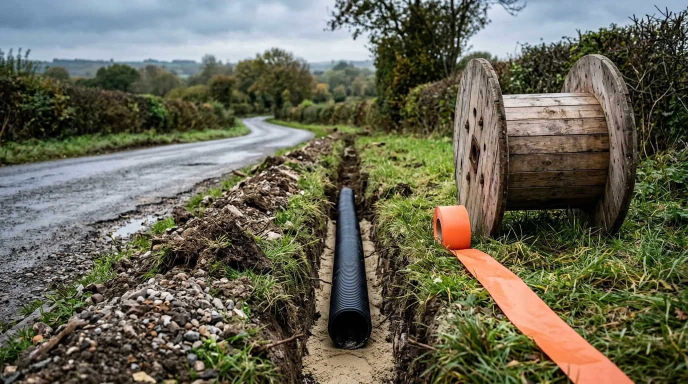
How deep is fiber optic cable buried? The published figures for buried fiber routes span roughly 70 mm where a shallow trenching method is used, 200–300 mm (8–12 in) for a residential drop in US carrier practice, and up to about 1,200 mm (48 in) where the route is a conduit run in outside-plant practice — and the number that applies to your route is set by whichever code, regulator or asset owner governs that surface, not by the cable. Every one of those instruments measures the same thing: the distance from the top of the cable or duct to finished grade.
That is the contradiction running through this topic: search results, carrier help pages and forum threads quote 24 inches, 30 inches, 8 to 12 inches and "just a few inches" for the same product, and they are all quoting real figures — from different rulers. This guide sets out what "depth" is measured to, which regime owns your route, the published numbers country by country, and what those numbers should change on the purchase order.
One caveat before the numbers: this is a summary of published engineering requirements for reference, not a code ruling. The authority having jurisdiction (AHJ), the road authority or the telecom regulator on your project has the final word.
How deep is fiber optic cable buried? What the number actually measures
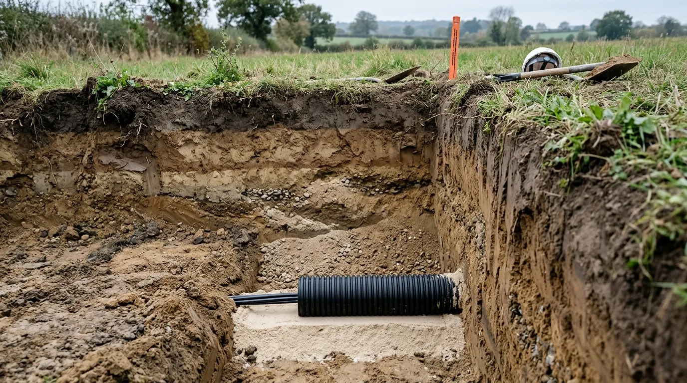
Fiber optic cable burial depth is measured as cover: the shortest distance between the top surface of the direct-buried cable, conduit or raceway and the top surface of finished grade. The definition is written into the US minimum-cover table itself:
"Cover" is measured between a point on the top surface of any direct-buried conductor, cable, conduit or other raceway and the top surface of finished grade, concrete, or similar cover.
The Canadian rule and the Australian cabling standard measure the same quantity, and both are quoted in full in the country section below.
Two consequences follow, and both cost money when they are missed:
- Cover is not trench depth. The trench floor sits below the cable, so a crew told to "dig 24 inches" and then dropping cable onto the floor delivers less than 24 inches of cover.
- Cover is not the depth printed on the drawing's survey stake. Grade changes: verges get re-surfaced, roads get overlaid, and a route re-graded by 100 mm silently changes the protection over the cable.
"Depth" is also sometimes used loosely for two constructs that are not cover at all: duct depth (to the crown of a duct) and micro-trench depth (a 300–500 mm slot cut into an existing road surface). Those are separate design choices with their own rules, and a specification that mixes them up will be resolved in the field by whichever number is easier.
Four regimes set the number — the cable does not
The reason there is no global figure is jurisdictional, not technical. Direct burial is regulated in four different ways depending on where the route sits:
- Electrical codes. In the United States and Canada, direct-buried cable depth is a minimum-cover requirement in the electrical installation code. These are enforceable and inspected, and the code's own scope rules decide whether a given cable is covered by the depth rows at all.
- Telecommunications regulators and cabling standards. Australia's cabling requirements for customer cabling are set in a standard registered by the Australian Communications and Media Authority — the number comes from a telecom instrument, not from an electrical code.
- Road-authority and industry practice. In the United Kingdom no statute fixes the depth of apparatus under a highway; the published figures are industry recommendations that asset owners are expected to follow.
- The asset owner's own standard. Where a network operator owns the route, its own construction standard governs — often expressed as a range and enforced contractually rather than by inspection.
That is why the same 24-fiber cable can be legally at 8 inches on one side of a property boundary and required at 24 inches on the other. It also means the first question for any route is not "how deep" but "who owns this surface, and what instrument do they enforce?" Once you know the regime, the number is a lookup.
For the cable side of the same question — whether a supplier's fire rating, UL listing or certification claim survives verification — the compliance cluster covers the document trail for verifying a fiber supplier's UL listing.
Burial depth by country: the numbers and where they come from
Five jurisdictions cover most export-facing fiber projects. How deep fiber optic cable is buried differs in each of them, and the instrument named in the middle column — not the cable — is what a specification should quote.
Jurisdiction | Instrument that sets the number | Minimum cover for direct-buried cable |
|---|---|---|
United States | NEC Table 300.5 (direct burial cables or conductors) | 24 in (600 mm) generally; 24 in under streets, highways, roads, alleys, driveways and parking lots; 18 in in a trench below 2-in-thick concrete; 18 in for one- and two-family dwelling driveways; 2 in in solid rock under 2 in of concrete |
Canada | CSA C22.1 Rule 12-012 → Table 53 | Table 53 value, keyed to wiring method and to whether the location carries vehicular traffic; permitted reduction of 150 mm where mechanical protection is placed above the installation |
United Kingdom | NJUG positioning guidelines (industry recommendation) | Footway/verge 250–350 mm; carriageway 450–600 mm; 350 mm minimum off the public highway |
Germany | Telekom Deutschland cable protection notice | Normal installation depth 40–100 cm; trenching, sawing and milling methods from 7 cm depending on class |
Australia | AS/CA S009:2020 clause 18.6 (ACMA-registered) | 450 mm under a public footway or roadway; 300 mm elsewhere |
United States. The minimum-cover table treats direct-buried cable as a single row — 24 inches (600 mm) in "all locations not specified below" — then adds rows for particular surfaces: 24 inches under streets, highways, roads, alleys, driveways and parking lots; 18 inches in a trench below 2-inch-thick concrete; and 18 inches for one- and two-family dwelling driveways and outdoor parking areas used only for dwelling-related purposes. One caveat on the shallowest row: in the rendering we checked, parts of the solid-rock row (2 inches of cover under 2 inches of concrete) are qualified "in raceway only", so a route that depends on that relaxation needs the code column read rather than the row summary. Optical fiber is covered by the code's optical fiber article rather than by the power articles, and how the depth rows apply to a dielectric cable is read differently in different jurisdictions — which is the practical reason a US carrier can publish 8 to 12 inches for a residential drop while the code table says 24. Allo, a US fiber operator, states plainly that main lines in easements and rights of way are buried two to four feet deep, while the drop to the house or pedestal may run 8 to 12 inches. Both figures are real; they describe different routes under different owners.
Canada. Rule 12-012 requires direct-buried conductors, cables or raceways to meet the minimum cover in Table 53, and defines cover as the minimum distance between the top surface of the cable or raceway and finished grade, with the table value keyed to wiring method and to whether the location is subject to vehicular traffic. The rule also carries two provisions that change field practice rather than the number: cover may be reduced by 150 mm where suitable mechanical protection — treated planking at least 38 mm thick, poured concrete or concrete slabs at least 50 mm thick — is placed in the trench above the installation; and direct-buried conductors must sit in at least 75 mm of screened sand or screened earth both above and below, with backfill particles no larger than 4.75 mm. Practical reading: the values sit inside a paid standard, so do not build a trench plan from a recollection of the table — the mechanism (vehicular or not, protected or not) is what determines the number you owe.
United Kingdom. The positioning guidelines state that there are no statutory obligations governing the position or depth at which apparatus should be laid within the highway, and that the recommended figures should therefore be adhered to wherever practicable. The communications rows give 250–350 mm in the footway or verge and 450–600 mm in the carriageway; off the public highway — footpaths, verges, uncultivated land and land not open to vehicular traffic — the recommended minimum is 350 mm, with deep ploughing by agreement. Guidance is not a licence to go shallow: the same document warns that existing apparatus should not be assumed to conform, so a locate before digging remains the reliable input.
Germany. Telekom Deutschland's cable protection notice is unusually direct about how much the figure varies: telecommunications cables are normally installed on a trench bottom at 40 cm to 100 cm, while newer methods go far shallower — trenching classes at 7–12 cm, sawing and milling classes at 20–30 cm, and other trenching at 30–50 cm. The notice is aimed at third parties working near the network, and its warning matters for buyers: positions in depth vary because of crossings, later changes to the surface cover, and groups of ducts wider than expected. Any assumption that "German fiber is at 60 cm" is a planning guess, not a requirement.
Australia. Clause 18.6 of the ACMA-registered standard sets underground customer cabling under a public footway or roadway at a minimum depth of 450 mm, measured from the finished ground or pavement surface to the top of the cable or conduit, and 300 mm elsewhere. Where soil conditions prevent 300 mm — solid rock, shale, or a crossing with another service — the standard allows a shallower installation under a covering of at least 50 mm of fine aggregate concrete. This is the pattern to look for in every jurisdiction: the number is not one value, it is a default plus a documented escape route, and the escape route has its own requirement.
One honest limitation: most national tables carry more rows than any public summary shows, and several sit behind paid standards. Where exposure is high — a road crossing, a river, a shared utility corridor — buy the standard and read the clause.
If the route instead runs overhead, the trade-offs move to span, sag and jacket performance, which is covered in the comparison of OFNP, OFNR and LSZH fire ratings — that is a fire-performance question, not a mechanical-protection one, and the two get mixed up constantly in specifications.
Burial depth by surface type: the rows that change the number
Same jurisdiction, different surface, different number. This is the table to hand to whoever is setting out the trench.
Surface or condition | Who sets the number | Minimum cover |
|---|---|---|
Private lawn or garden, residential drop | Network operator's own standard | As little as 8–12 in in US carrier practice; 300 mm in Australia; 350 mm in the UK off the public highway |
Public footway or verge | Road authority and industry guidance | 250–350 mm in the UK; 450 mm in Australia |
Driveways and parking areas (vehicular) | Electrical code, then road authority | 24 in in the US, reduced to 18 in for one- and two-family dwelling driveways; 450–600 mm in the UK; 450 mm in Australia |
Public roadway | Road authority and highway standards | 24 in in the US; 450 mm in Australia; 450–600 mm in the UK; at least 800 mm to the crown of a duct in outside-plant practice |
Agricultural land subject to ploughing | Asset owner, by agreement | Agreed per project; 800 mm to duct crown in outside-plant practice |
Solid rock | Code allowance with concrete protection | 2 in under 2 in of concrete in the US; 300 mm with a concrete slab in outside-plant practice |
Alongside high-voltage power | Separation rule rather than depth | 600 mm horizontal, 300 mm vertical in outside-plant practice |
Below the frost line | Design input where frost heave can move the soil | Deeper than the local frost penetration |
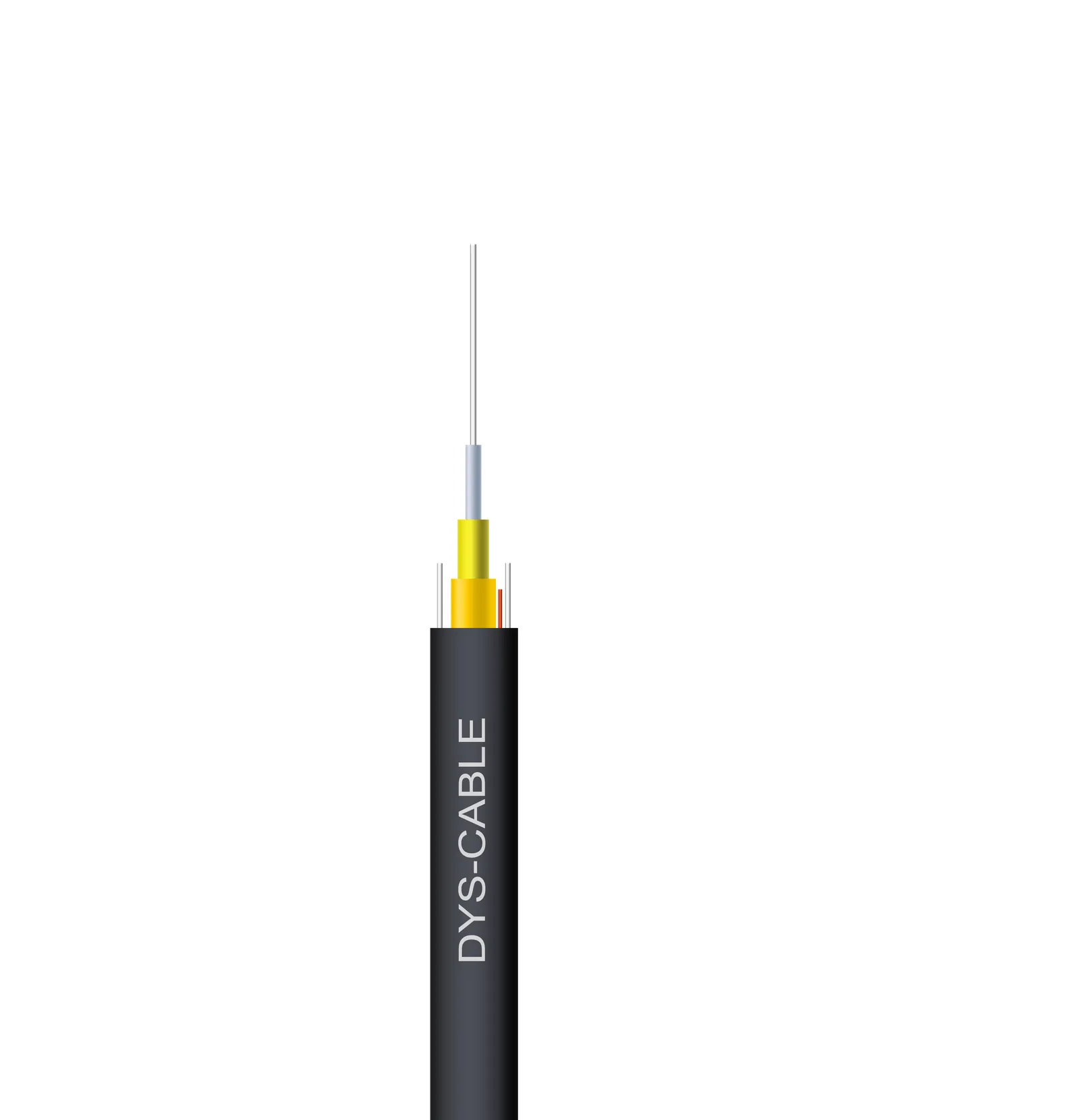
The residential row deserves the warning. A drop cable at 8–12 inches is a design choice matched to the surface above it: a mown lawn with no vehicular load, under a route the operator can locate at any time. Move the same 8-inch assumption under a driveway and it becomes a maintenance liability — and the cable that belongs there is a different construction. The tight-buffered indoor/outdoor drop cable used for residential drops, for example, is specified for aerial, direct-bury or conduit installation and all-dielectric construction, which is what makes it usable in a shallow trench without a ground connection — see the indoor/outdoor drop cable for aerial and direct-bury routes. What a shallow drop cannot survive is a future change of surface use, so record the route and the depth for whoever digs next.
Two rows in that table are separation rules rather than depth rules: the clearances to high-voltage power, and the requirement to lay a detectable marker above the route so it can be found again. Neither substitutes for a cover value.
From depth of cover to trench depth: the step most crews skip
Once the required cover is known, the trench floor depth follows from arithmetic that nobody writes on the drawing.
Take a 144-fiber steel-tape armored outdoor cable with an outer diameter of about 22.5 mm, a required cover of 600 mm, a 100 mm bedding layer under the cable, and the paddings and backfill lifts the construction practice calls for. To deliver 600 mm of cover over the cable top, the trench floor must be cut roughly 600 + 22.5 + 100 ≈ 722 mm below finished grade. Run the same route with a 10.5 mm cable and the floor moves less than 15 mm — which is why the cable's own diameter belongs in the calculation, not just in the bill of materials.
The independent reference for outside-plant work makes the same point in a different direction:
It is immensely important for trenches to be excavated to such a depth that the crown of the duct has at least 800 mm (32 inches) of backfill cover, in all soil conditions, except for where hard rock conditions are encountered. — Fiber Optic Association, underground cable plant construction
That reference also fixes the quantities that most often get improvised on site: bedding and padding of granular, non-cohesive material graded between 0.6 mm and 13 mm; backfill placed in layers no thicker than 300 mm, each compacted before the next; the marker or warning tape laid after the first compacted lift; and a conductive marker tape no more than 300 mm below the surface if it is to be detectable at all. The same page gives conduit runs a usual burial depth of 1–1.2 m (3–4 ft), which is where the top of the range in this article comes from. In hard rock the reference permits a relaxation, but only with a 75 mm reinforced concrete slab over the padding — protection is traded against depth, not simply dropped.
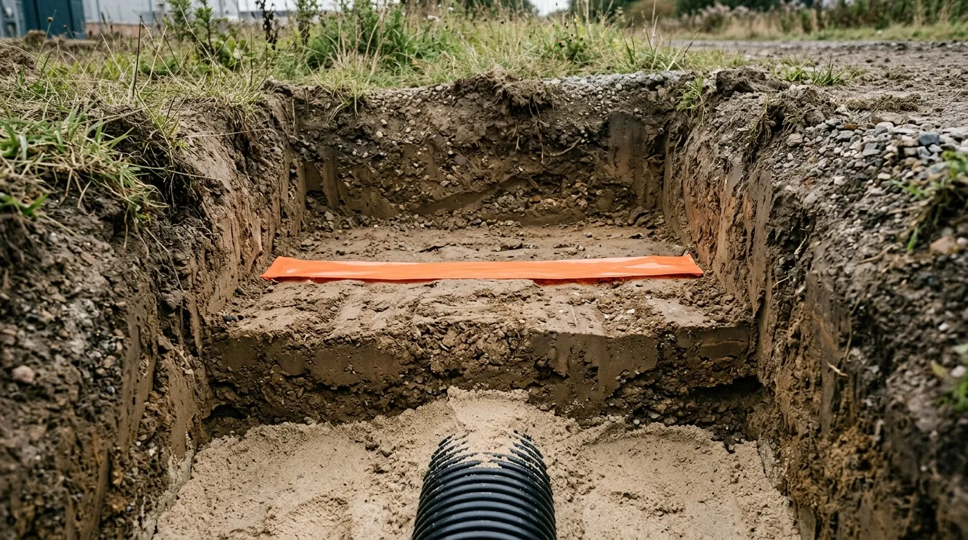
Two field errors account for most of the gap between the drawing and the installed route: cable laid on the trench floor before the bedding is placed, and backfill with excavated rock that punctures the jacket during compaction. A depth check before backfill and a photograph of the tape position cost almost nothing.
What the depth number should put on your purchase order
The depth row you just looked up translates directly into cable specification. Six lines are worth writing on the order, because each one limits what a supplier can substitute:
- The cover value and the surface above it. Not "direct burial" but "600 mm cover, public roadway" or "300 mm cover, private lawn". The row is the requirement.
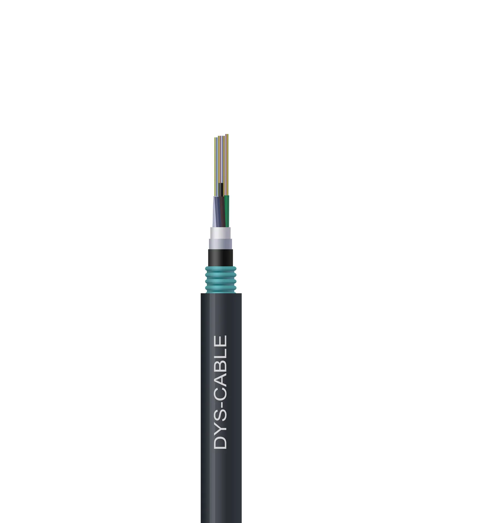
- Outer diameter. It eats into the cover arithmetic, and it drives duct fill if the route also needs conduit. A steel-tape armored outdoor cable in DYS Fiber Optic's range runs from 14.5 mm at 12–48 fibers to 22.5 mm at 122–144 fibers; a lighter single-jacket outdoor cable of the same family starts at 10.5 mm.
- Armor and sheath construction. Corrugated steel tape over a PE outer sheath is what answers rodent attack and crush load; a double-jacket construction adds the moisture margin that long-lived buried routes need. The fiber unit inside a direct-buried outdoor cable is normally a stranded loose-tube design, with the fibers free to move so they stay stress-free under the longitudinal loads a buried route sees — the tight-buffered construction belongs at the other end of the same route, in the drop cable.
- Crush resistance in N/100 mm, short and long term. This is the number that matches the load above the cable. The armored outdoor construction above is specified at 3,000 N/100 mm short-term and 1,000 N/100 mm long-term, against 1,000 / 300 for a single-jacket steel-tape cable — a threefold difference on the load case, quoted on the steel-tape armored outdoor cable data sheet.
- Tensile strength, short and long term. Relevant for ploughing, pulling through duct and any route installed before the trench is finished.
- Water-blocking and drum length. A high water table or a flood-prone route calls for a water-blocked core; standard drum lengths of 2–3 km with other lengths on request keep splice counts where the design put them.
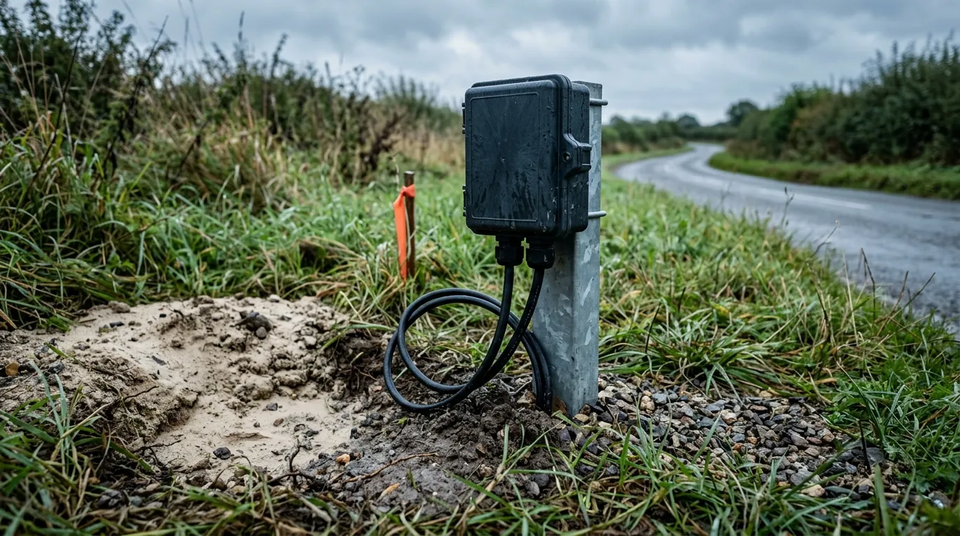
The last piece of the depth decision is what sits at the ends of the route. Where a buried drop terminates, the outdoor terminal box family and its access pit become part of the cover calculation: the box is set at or near grade while the cables enter from below, and that transition is where a shallow route loses its protection. Whichever design the project uses, the pit detail is a depth decision, not a hardware detail.
FAQ: the questions the search results answer badly
Can I bury my own fiber optic cable? You can buy direct-burial cable and dig a trench, but you do not get to choose the depth when the route runs in a utility easement or right of way — the network operator's standard governs there, and it may be far shallower than the code table. On private property with no easement, the depth rules of the governing code still apply, and a locate request before digging is the part most homeowners skip.
Is 6 inches deep enough? Not as a design value for a shared route. Six inches is below every general minimum quoted in this article; the figures that do fall below it are relaxation values whose reduction is bought with protection the soil alone does not provide — 2 inches of cover in solid rock under 2 inches of concrete, 300 mm in hard rock with a 75 mm concrete slab, and the 70 mm end of Germany's shallow-trenching classes, which apply where the surface and the method are controlled. A six-inch residential drop in a yard may survive for years, right up to the first aerator or spade, which is how most accidental cuts are recorded.
How deep do carriers bury residential fiber? Practice varies by operator, not by code: one US operator publishes 8–12 inches for the drop and 2–4 feet for main lines. Ask the operator for its construction standard rather than assuming a national figure.
Does fiber need conduit if the cable is armored? Not necessarily — steel-tape armored cable is designed for direct burial. Conduit buys something different: the ability to pull a replacement or an additional cable without re-excavating. The trade-off is set out in the comparison of direct burial against conduit.
What happens if a buried cable is cut? The repair is a splice at the cut point plus restoration of the surface, and the cost scales with depth and surface class rather than with cable price. Route records, service loops at handholes and a known drum length in stock are what shorten the outage; the field procedure is covered in splicing a damaged fiber cable.
Which number should go in a specification? The one from the instrument that governs the surface, quoted with its clause, plus the trench-floor arithmetic that delivers it. A specification that says "buried to code" transfers the decision to whoever is holding the shovel.
If your route crosses more than one jurisdiction or market, the depth question quickly becomes a compliance question: the same project may need a code-compliant cover figure in one country, a cabling-standard figure in another, and certification documentation for the cable itself in both. The fiber optic certifications and compliance guide covers the document side — UL, CPR, Anatel and TL 9000 — so that the cable arriving on site matches the number the trench was cut to.