
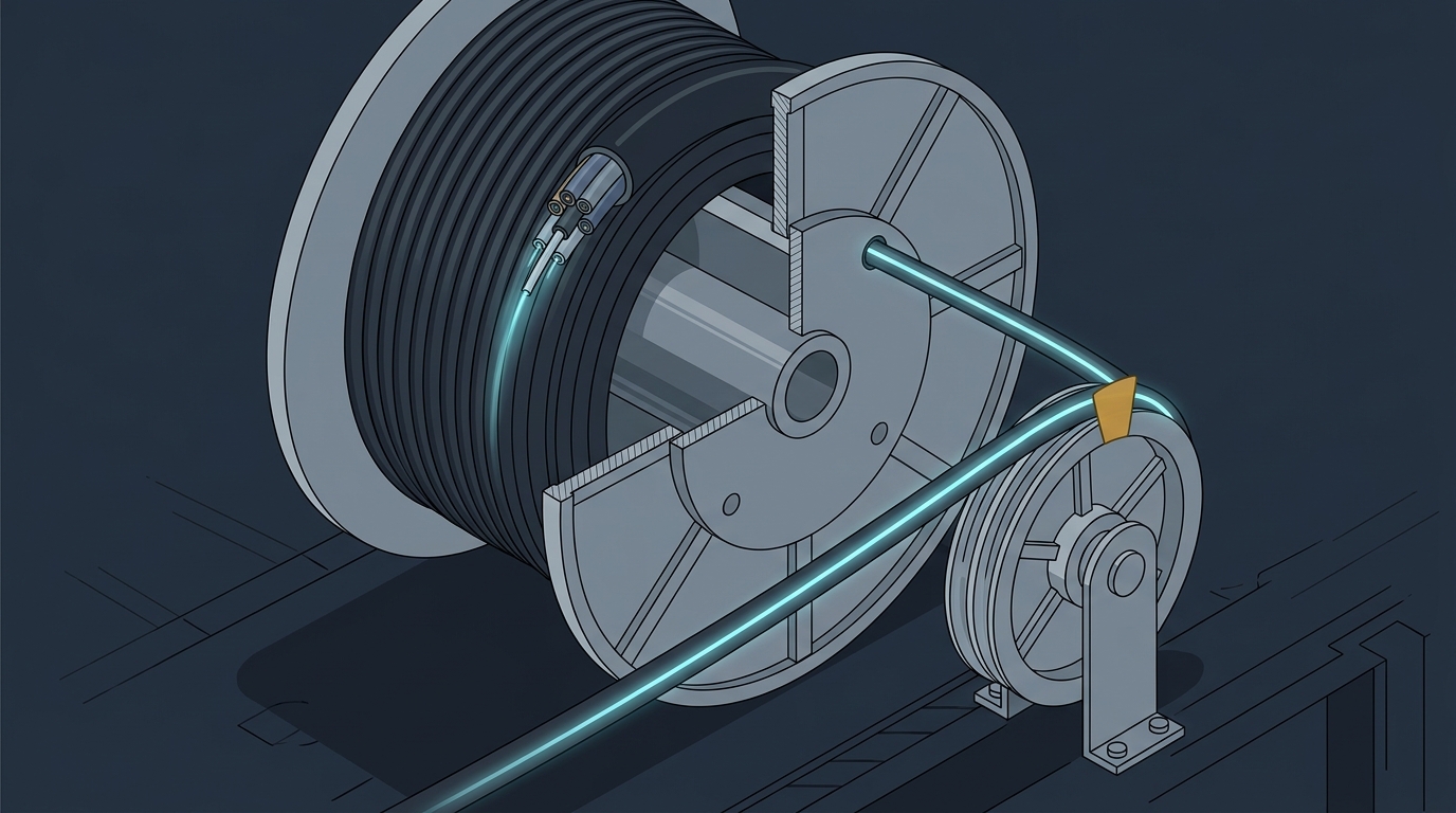
Installation
Fiber Optic Bend Radius: Minimums by Cable Type
Ask five installers for the minimum bend radius of a fiber optic cable and you will get the same answer five times: 20 times the cable diameter while pulling, 10 times once it is in place. Ask them to show you where that number appears on the reel they are about to pull, and the room goes quiet.
That gap is where projects lose money. The 20D/10D pair is a rule of thumb, and a lot of cable in current production does not use it. Manufacturer datasheets specify 20D/15D, 20D/10D, 15D/10D and 30D for cables of comparable diameter. Put the wrong pair into a technical agreement and you will reject compliant cable, or accept cable that was never meant to survive your route.
Here is how to read the numbers you actually have, how they change with cable construction, what exceeding them does to the light, and how to prove on a test set that a bend — not something else — is eating your loss budget.
Bend Radius vs Diameter: The One Mistake That Doubles Your Number
Bend radius is the distance from the center of the curve to the inside surface of the cable. Bend diameter is that distance doubled. Cable diameter is a third, unrelated quantity — the thickness of the cable itself.
Multipliers on a datasheet apply to cable diameter and produce a bend radius. A 14.5 mm cable with a 20D loaded specification must never be curved tighter than 290 mm. Say "bend diameter" instead and you have told your crew the limit is 580 mm, which is a different job with different hardware.
This is not pedantry. The Fiber Optic Association keeps a dedicated section on the radius/diameter confusion in its cable bend radius reference because it keeps producing wrong numbers in the field — especially around pulleys and capstans, where the hardware you buy is specified by diameter. Their worked example is blunt: if the bend radius limit is 20 times the cable diameter, a pulley the cable runs over must be at least 40 times the cable diameter, because you are converting a radius requirement into a hardware diameter. The same conversion applies to every storage loop, every manhole coil, and every service loop you leave behind.
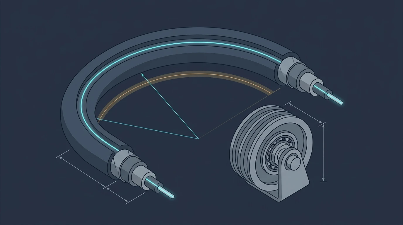
One more definition to settle before you buy anything: the multiplier applies to the cable's outer diameter, not the fiber's. A 250 µm bare fiber and a 14.5 mm armored outdoor cable carry the same glass inside and completely different bend limits. Fiber-level and cable-level specifications are separate documents, and only the cable-level one governs what your crew can do with the reel.
Loaded vs Unloaded: Why Every Cable Has Two Bend Radius Numbers
Every cable has two minimum bend radius specifications, and they answer two different questions.
Loaded — also called dynamic, under tension, or short-term — is the limit while the cable is being pulled, blown, or otherwise moved. It is the larger number because the cable is simultaneously bent and stretched, and the two stresses add.
Unloaded — static, long-term, or installed — is the limit once the cable is secured and no pulling tension remains. It is the smaller number, which is why the coil you leave in a handhole can be tighter than the sheave you pulled it over.
The loaded number is bigger because of what the glass is doing. Bend a fiber and the outside of the curve goes into tension while the inside goes into compression. Pull the cable at the same time and you add axial tensile load on top of that bending stress. Cable makers set the loaded limit high enough that the fibers survive the combined stress without microcracking; the unloaded limit is set by the loss and long-term reliability budget instead.
The general case is 20 times the cable diameter under tension and 10 times after installation, with an important qualification: some cables are specified at 15 times while being pulled, some are 15 times in both states, and always the manufacturer's specification for the specific cable wins. Proterial, which manufactures under the Hitachi Cable heritage, publishes a 15X loaded / 10X static example in its fiber bend radius FAQ: for a 0.47 in cable the loaded limit works out at 7.05 in and the static limit at 4.7 in. Read those as bend radii, which is what the multiplier produces — the pipe, duct or sheave the cable runs against is specified by diameter, so the hardware number doubles, exactly as the conversion above requires.
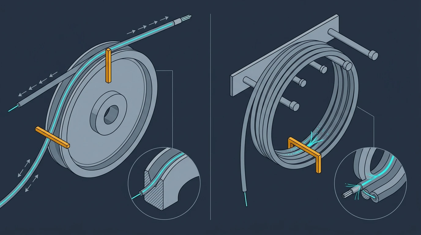
Notice what the loaded number is not for. It is not a limit you can relax once the puller has stopped and the cable "looks fine." Pulling a cable around a bend tighter than its loaded limit can crack fibers or deform the jacket without leaving any visible sign, and the failure shows up as a loss spike weeks later. That is why the loaded limit belongs in the pull plan rather than in a post-installation checklist.
For how bend radius sits alongside pulling tension, crush load and splice planning as the mechanical limits that govern a pull, the installation handbook hub covers the full sequence.
Fiber Optic Bend Radius Minimums by Cable Type
This is where the rule of thumb stops being useful. The minimum bend radius for fiber optic cable is not set by the glass; it is set by the cable construction wrapped around the glass.
Construction | What the bend load lands on | Typical published multiplier (loaded / unloaded) | Why |
|---|---|---|---|
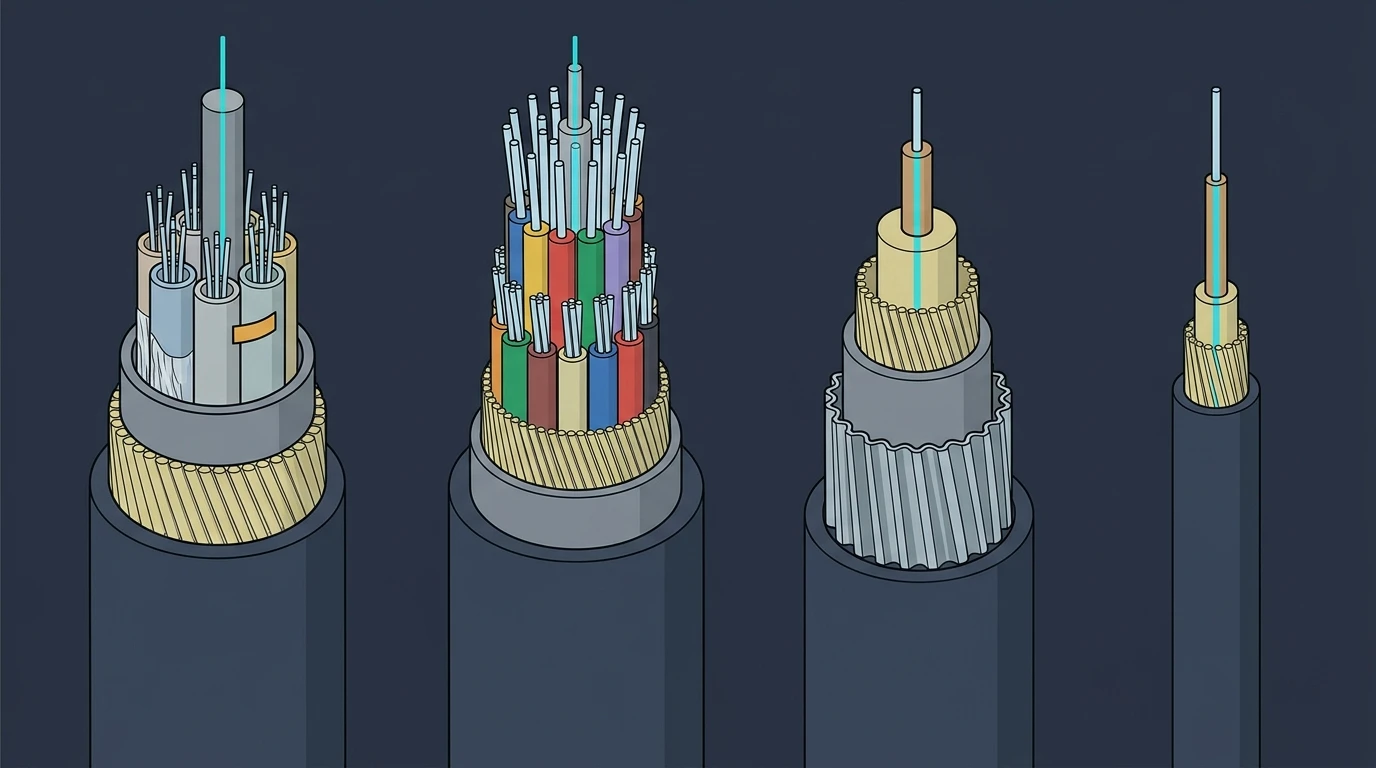
Loose-tube outdoor cable | Loose tubes with room to move inside the jacket; fibers are not bonded to the tube | 20D / 15D is common in current production | Each tube can shift slightly under bend, which spreads strain, but the fibers have no strain relief of their own |
Tight-buffered / distribution cable | The 900 µm buffer is bonded to the fiber, so bend strain reaches the glass directly | 20D / 15D typical; the fiber inside may itself be rated to 10 mm or 7.5 mm | Strain goes straight to the fiber, so the fiber's own bend grade sets the floor |
Armored cable | Interlocking or corrugated metal tape resists crush and rodent damage but adds a stiff, high-modulus layer | Usually the same multiplier as the unarmored equivalent, but the diameter is larger — so the absolute radius is larger too | Stiffness lives in the armor, which does not bend easily and does not shield the fiber from curvature |
Single-fiber patch cord / jumper | Only the 900 µm buffer and the fiber inside it | Varies widely: 20D loaded / 10D static on some bend-insensitive cords, and 30D with no state published on stainless-steel-armored simplex | The smallest cable in the catalogue often has the least forgiving multiplier |
Concrete numbers from DYS datasheets show what those differences look like in millimeters:
- A GYTS loose-tube outdoor cable, 10.5 mm in diameter, is specified at 20D dynamic / 15D static — 210 mm while pulling, 157.5 mm installed.
- The same family in a GYTA53 armored version, 14.5 mm, keeps the 20D/15D multiplier, but the absolute numbers rise to 290 mm and 217.5 mm.
- A FTTP tight-buffered indoor/outdoor drop cable, 4.0 × 7.0 mm, is also 20D/15D — 80 mm and 60 mm on the small dimension.
- A 3.0 mm stainless-steel-armored simplex cable is specified at ≥30D, or 90 mm, because the flexible steel tube that gives it crush resistance also refuses to bend.
- A data-center MPO/MTP assembly with an SNMT connector is specified at 20D dynamic / 10D static instead — the loose-tube rule does not apply, because the cable is a tight-buffered ribbon inside a small jacket.
Two cables in that list are almost the same size and half again apart in the radius they tolerate: the 4.0 mm FTTP drop cable allows a 60 mm radius, while the 3.0 mm armored simplex demands 90 mm. The thinner of the two needs more clearance, because the steel tube inside it refuses to deform.
The multiplier is set by the cable construction, and the absolute radius follows from the cable's outer diameter. A supplier who quotes one number without saying which state it belongs to has not given you a specification.
Premises standards take the same view. The TIA-568 fiber cabling requirements, as summarised in the FOA's reference page for the standard, set a fixed 25 mm bend radius after installation and 50 mm while pulling at 222 N for horizontal cable with 2–4 fibers, and a 10× unloaded / 15× loaded multiplier for other premises cable — values that vary with cable construction and fiber count rather than one global multiplier, which is why a patch cord in a cabinet and a 144-fiber trunk in the same room are not governed by the same number.
If you need the loose-tube versus tight-buffered distinction in more depth — which applications suit which, and how fire ratings intersect with construction — that is a selection question rather than a bend question, and the cable types selection guide works through it. For bend purposes the takeaway is narrower: the construction sets the multiplier, and the construction also sets the diameter the multiplier is applied to. Two cables that look the same size on a spec sheet can differ on both counts.
Why 20D/10D Is a Floor, Not a Law
Treat 20D/10D as the number you use when you have nothing else. The moment you have a datasheet, the datasheet wins — and it is a contractual document, not a suggestion.
Reading a bend radius specification properly means pulling four fields out of it:
Field | Why it matters | What goes wrong if you skip it |
|---|---|---|
Loaded multiplier | Governs the pull plan: sheave diameters, bend shoes, conduit entry angles | Crew uses the installed number during the pull and over-bends every transition |
Unloaded multiplier | Governs final routing: tray bends, cabinet entry, slack coils | Crew leaves a coil tighter than the cable allows, and you find it at acceptance |
Test method and conditions | Tells you what "20D" was tested against — bend test procedure, number of turns, wavelength, and the permitted attenuation increase | You compare two datasheets that measured different things and pick the wrong cable |
Temperature range for installation | Cold cable is stiffer and less tolerant of bending; ask the supplier for the installation temperature range on the datasheet | Winter installations run to a plan that worked in summer |
That third row is the one buyers miss most often. A bend test result is only meaningful with the method attached: at cable level, the mechanical test series in IEC 60794-1-21 covers the bend procedures used to qualify a cable, and for outside plant products Telcordia GR-20 sets the requirements a carrier-grade cable has to meet. When you compare two suppliers, compare the test conditions before the numbers — a 10D claim measured under mild conditions and a 15D claim measured under harsher ones may describe the same cable.
The other thing to understand is that load-state limits are not interchangeable. A supplier telling you "our cable is 15D" without saying whether that is loaded or unloaded has told you nothing you can build from — and that ambiguity is what gets argued about at acceptance, when the trench is already backfilled.
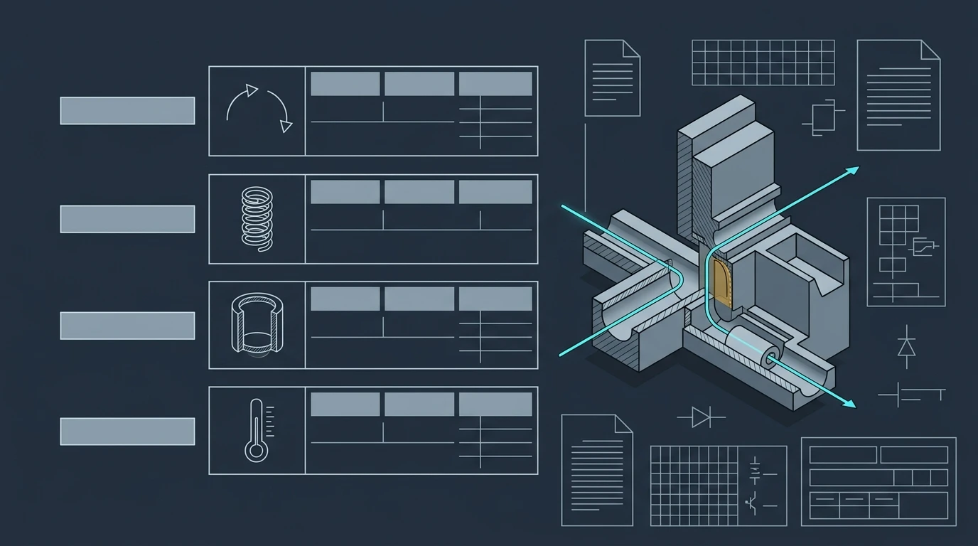
If you want to see how the values sit next to the rest of a product's specification, the GYTA53 armored outdoor cable datasheet shows the fiber-count and diameter table next to the tensile, crush and bend radius columns. That layout is what you should ask for from any supplier you evaluate.
What Actually Happens When You Exceed It: Macrobend vs Microbend Loss
Bend too far and light leaves the fiber. The mechanism matters, because the loss you measure is not the same thing as the damage you cause.
Light in a single-mode fiber does not travel entirely inside the core. The guided mode's field extends into the cladding, and how far it extends depends on wavelength — longer wavelengths are less tightly confined. At a bend, the outside of the curve has to carry the mode over a longer path than the inside in the same amount of time, and past a certain curvature the field on the outside can no longer keep up. It couples out of the core into the cladding and coating, where it is lost as a macrobend.
Because confinement weakens with wavelength, macrobend loss is wavelength-dependent. A bend that costs almost nothing at 1310 nm can cost several tenths of a decibel at 1550 nm. That single fact drives most of the testing advice further down this page, and it is why a link can pass at one test wavelength and fail at another.
Microbends are the other half of the picture, and they do not come from the route at all. They come from lateral pressure: a cable tie ratcheted down onto a bundle, a cable pinched between a tray edge and a rack, a jacket pressed against a rough surface. The fiber is not visibly curved anywhere, but it is deformed hundreds of times along its length, and each deformation couples a little light out. The result is distributed loss — a fiber that measures uniformly lossier than its attenuation specification, with no discrete event to find.
The practical difference is what you can do about each one:
- A macrobend is a discrete, locatable event. It sits in one place on the route, it appears as one event on a test trace, and if it is purely a curvature problem, releasing the bend usually recovers most or all of the loss.
- A microbend is distributed and has no single location. You find it by ruling things out — comparing measured attenuation against the cable's specified attenuation, and inspecting how the cable is secured along its whole run.
- A bend that has damaged the fiber is neither. If stress has cracked the glass, releasing the curvature does not restore the loss, and the cable's reliability is permanently reduced. Sustained stress accelerates the slow crack growth that eventually breaks an over-stressed fiber, which is why the long-term bend radius is a service-life specification and not just a loss specification.
The Fiber Optic Association's loss and attenuation reference for optical fiber testing treats bending losses as an additional source of measurement uncertainty that has to be controlled before any attenuation figure can be trusted, and advises respooling tightly wound cable with less tension before measuring it.
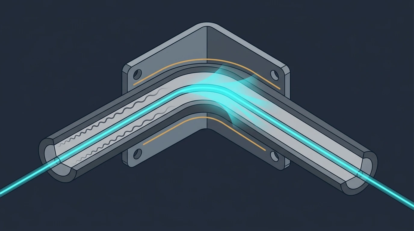
For how bend loss fits into the rest of a link's loss budget alongside connectors and splices, the comparison between insertion loss and return loss covers the accounting side. Bend loss is the component that behaves least like a fixed number, because it depends on the route rather than on a component.
Bend-Insensitive Fiber and the G.657 Categories
If your route genuinely cannot respect the standard limit — a dense patch panel, a riser with tight corners, a module enclosure where the slack has to sit in a 50 mm well — the fix is a different fiber, not a bigger box.
Bend-insensitive fiber uses a modified refractive index profile, typically a trench around the core that reflects escaping light back inward, so the mode stays confined at curvatures where a standard fiber would leak. The governing standard is ITU-T G.657, which defines bend-insensitive single-mode fiber in categories with progressively tighter capability: G.657.A1 is qualified down to a 10 mm bend radius, A2 to 7.5 mm, and B3 to 5 mm. ITU-T G.652 remains the baseline standard single-mode fiber, and G.657.A1 and A2 are built to be compatible with G.652 links, so you can mix them without changing your splicing plan.
What matters commercially is which category you are being quoted. "Bend-insensitive" is a marketing phrase; G.657.A1 and G.657.B3 are specifications that differ by a factor of two in the radius they tolerate, and the price moves with the category. If your design assumed a 5 mm radius and the supplier ships A1 fiber, you have a cable that meets the word and misses the requirement.
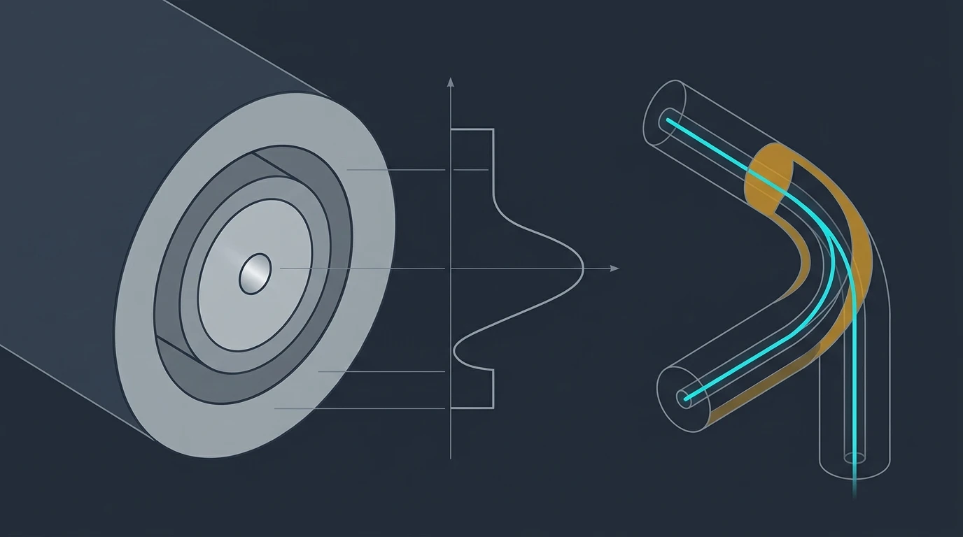
Two cautions. First, the fiber grade and the cable grade are separate limits — B3 glass inside a stiff cable construction still has to respect the cable's multiplier, because the construction is what carries the strain. Second, bend-insensitive glass solves the optical side only. A cable bent past its limit can still be mechanically damaged, still have its jacket deformed, and still fail. The glass is more forgiving; the assembly is not.
One term you will meet elsewhere: some sources call the point where bend loss starts climbing steeply the critical bending radius and put it at roughly eight times the cable diameter. That is the same knee in the loss curve, described from a different test — not a third specification sitting on top of the loaded and unloaded limits. Treat any critical radius quoted without a test method as an approximate indicator, and go back to the two state-specific values when you have to make a decision.
That covers the glass. The other half of the problem is what happens to the cable while it is being moved into place.
How to Route and Pull Without Exceeding the Limits
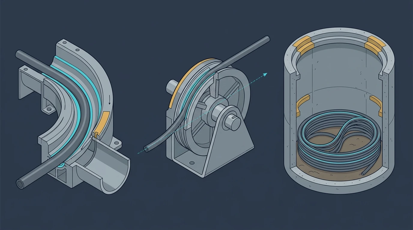
Three locations cause most bend radius violations on real projects. Each has a specific fix.
1. The transition points. Conduit mouths, handhole entries, cabinet entries and tray exits are where a straight run becomes a corner — and where a crew that has been pulling in a straight line all morning suddenly introduces a radius nobody calculated. Protection at conduit ends and at the mouth of a manhole or handhole is standard practice, using sheaves, quadrants or flexible duct. The Fiber Optic Association's general installation guidelines are explicit that pulling tension, minimum bend radius and crush load must all stay inside specification during installation — its own summary of how that gets broken is that cable "can be broken when kinked or bent too tightly, especially during pulling."
2. The pull itself. Pull by the strength members, never by the jacket or the glass, unless the manufacturer explicitly approves jacket pulling for that design and you are using an approved grip. Use a swivel pulling eye so the cable cannot twist. Keep the pull as straight and uniform as you can, and align the capstan with the direction of the pull instead of letting the cable turn a corner to reach it. When a run is long enough that you have to lay cable out in loops, lay them as figure-eight loops so the cable does not twist on itself.
3. The slack you leave behind. Post-installation coils in handholes, aerial service loops and cabinet slack are the last chance to get this right and the easiest place to get it wrong, because the cable is unloaded and nobody is measuring. Remember the conversion: an unloaded limit of 15D means a coil diameter of 30 times the cable diameter, not 15. For a 14.5 mm cable that is a 435 mm coil — bigger than most people picture when they say "just leave a bit of slack." The Fiber Optic Association's outside plant installation guidance is a useful checklist for the handhole and manhole end of the job specifically.
A few habits that prevent all three:
- Write the numbers on the pull plan, in millimeters and inches. "20D" is not a field instruction; "minimum sheave diameter 580 mm" is.
- Size the hardware before the pull, not during it. Sheave, quadrant and bend shoe diameters come from the loaded multiplier — applied to the diameter of the specific reel you received, which can change between fiber counts in the same product family.
- Watch the temperature. Cable routed in cold weather is stiffer, so a winter pull on the same route needs more clearance than the summer one did. Optical Cable Corporation's storage and handling guide is specific about the routine: in cold weather, store the reels in a heated area for at least 24 hours before installation, so the cable does not go into the pull cold.
- Do not use a cable tie as a bend fixture. Pulling a bundle tight against a tray corner creates a radius nobody designed and the lateral pressure that produces microbend loss along the whole bundle.
- In conduit work, choose the path with fewer direction changes. Less friction also means less pulling tension, which keeps you further from the loaded limit. The trade-off between the two routing methods is covered in the direct burial versus conduit comparison if the route is still open.
One trade-off to name explicitly, because it is the reason tight bends keep happening: designing to the more conservative multiplier is not free. A 15D long-term limit instead of 10D means every coil, tray bend and cabinet entry needs half again as much space, and in a crowded riser or a small outdoor cabinet that space does not exist. That pressure — not ignorance — is what pushes crews to the tighter number. Which is exactly why the number has to come from the datasheet for the cable in hand, rather than from a habit that was formed on a different product.
Reading a Bend on an OTDR Trace
An OTDR is the right instrument for confirming a bend, because it can separate a discrete event from distributed loss — and because it lets you test the same fiber twice.
The key visual cue: a bend is a non-reflective loss event. A connector or mechanical splice produces a spike of reflected light followed by a drop in the backscatter level. A macrobend produces a step down in the backscatter trace with no reflection spike at all — the trace simply drops to a lower level and continues. Reflective event with a spike means a connector or a break; non-reflective step means a bend, a tight coil, or a genuinely clean splice.
Four things to do once you see that shape on the trace:
- Test at the longest wavelength your link uses. Macrobend loss grows with wavelength, so a bend that is invisible at 1310 nm may be obvious at 1550 nm. If you test at one wavelength only, test where the effect is largest.
- Measure from both ends. OTDR loss readings for any event depend on the backscatter characteristics of the fiber on each side of it, so a single-ended trace can overstate or understate the event loss. Bidirectional measurement, averaged, is the standard way to reach a defensible number — and a defensible number is what you need if the finding is going to support a rework claim.
- Relieve the bend and re-test. This is the diagnostic that separates recoverable curvature from damage. If the event loss disappears once the cable is relaxed, you had a routing problem. If it stays, the fiber or the cable construction has been damaged, and re-routing will not fix it.
- Look at the whole route, not just the event. A bend at a known transition point is one story; a non-reflective step in the middle of a straight run suggests the cable went around something you did not plan for — a conduit offset, a duct that has shifted, or a sharp edge inside a cabinet.
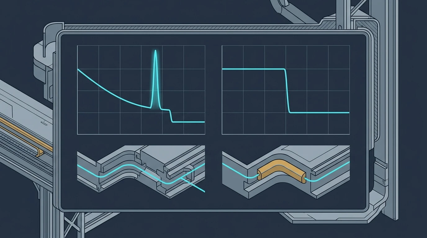
Read the trace before you chase the number. The Fiber Optic Association's OTDR testing quick start walks through how loss events and reflectance are read on a trace, which is the part that tells you whether the event in front of you is a bend or something else entirely. Bend events also sit inside the link's total loss budget, and the acceptance math — how many splices and connectors you can afford before the budget is spent — is worth working through before you start arguing over a few tenths of a decibel. The fiber optic cable testing guide covers that workflow, where an OTDR result becomes a documented acceptance decision rather than a disagreement.
What to Write Into Your Purchase Spec
Most bend radius content online is written for the crew holding the pull rope. Buyers get the same advice, which is usually why bend radius clauses in technical agreements run to a single line: "minimum bend radius: 20× cable diameter during installation, 10× after installation." That line is unenforceable against modern cable, and it is why acceptance arguments happen.
Replace it with clauses that can actually be checked:
Clause | Wording that works | What it prevents |
|---|---|---|
Separate states | "Minimum bend radius shall be specified separately for the loaded (installation) and unloaded (long-term) condition." | A single ambiguous number argued about at acceptance |
Test conditions | "The bend radius specification shall state the test method, number of turns, test wavelength, and the maximum permitted attenuation increase at that test." | Comparing a 10D claim tested loosely against a 15D claim tested strictly |
Per-construction values | "Values shall be provided for each cable construction and each diameter in the supplied range, not a single figure per product family." | A family-level number that does not match the reel delivered |
Temperature | "The installation temperature range shall be stated, together with the minimum bend radius the supplier specifies at the low end of it." | Cold-weather pulls run to a summer plan |
Traceability | "Final bend radius compliance shall be verified by OTDR with bidirectional measurement at the highest link wavelength, with traces supplied as acceptance records." | Disputes over whether the cable or the installation caused the loss |
A supplier that can answer all five clauses from published documentation is a supplier you can hold to a specification. A supplier that cannot answer the second one is telling you the number was never measured under a defined method — and a number without a method is a claim, not a limit.
If you want to see how a manufacturer publishes this — multiplier, diameter, fiber count and test conditions in one table — the FTTP tight-buffered drop cable datasheet and the stainless-steel-armored simplex cable datasheet are useful reference points, precisely because their multipliers differ from each other's. If you are drafting a technical agreement and need the loaded value, the long-term value, the test method behind both and the installation temperature range in one document, tell us the cable and the diameter and we will return the specification tables against it.
FAQ
Can fiber optic cable bend 90 degrees?
Yes — 90 degrees of direction change is fine if the curve is spread over enough space. What matters is the radius, not the angle. To turn 90 degrees without exceeding a radius of R, the corner needs roughly R of clearance on the outside of the turn. A 14.5 mm loose-tube cable with a 15D unloaded limit needs a 217.5 mm radius, which means a quarter-circle sweep occupying about 218 mm in each direction. What fails is a sharp corner or a kink, not the 90 degrees.
How much loss is acceptable in a fiber link?
That depends on the budget you designed, not on a universal number. Bend loss counts toward the same total as connector pairs, splices and fiber attenuation. Where a bend is the suspected cause, treat a non-reflective event that appears at the longer test wavelength, disappears when the bend is relaxed, and is absent on a neighboring fiber in the same bundle as a routing defect to correct rather than a budget item to absorb.
What is the minimum bend radius for Cat6 cable?
A different rule entirely, and worth keeping separate. ANSI/TIA-568.0-D requires a minimum bend radius of four times the cable diameter for 4-pair balanced twisted-pair cable, both during and after installation, as this bend radius reference sheet summarises — for a typical Cat 6A cable around a quarter of an inch in diameter, that puts the minimum at roughly 1 in, which is the clearance a J-hook or a tray bend has to provide. Compare that against a fiber multiplier and the fiber limit is the more demanding of the two for cable of the same thickness — 10× to 20× against copper's 4× — which is why a mixed copper-and-fiber bundle has to be built to the fiber limit.
What is the minimum bending radius for fiber optic cable?
There is no single figure. The multiplier is set by cable construction, and the absolute radius follows from the cable's outer diameter. Loose-tube outdoor and tight-buffered distribution cable are commonly published at 20D during installation and 15D long-term; some data-center assemblies are 20D/10D; armored simplex cable can be specified at 30D or more. Design to the number printed on the datasheet for the exact cable and diameter you are installing, and verify against the unloaded value, because that is the state the cable spends its service life in.
Bend radius is the cheapest failure mode on a fiber project to prevent and one of the most expensive to discover late. The next time you write or approve a bend radius clause, spend five minutes asking the supplier for the loaded value, the unloaded value, the test method behind both, and the temperature caveat. That request alone separates suppliers who measure from suppliers who quote a rule of thumb.