
Connectors
Fiber Optic Adapters: Types, Couplers, and Selection
A fiber optic adapter is the cheapest part on the panel and the one that decides whether the link passes. It has no ferrule of its own, it terminates nothing, and a vendor's own specification sheet rates its contribution at 0.05 dB typical — yet every connector you own is judged by the connection it makes through an adapter. The same part also answers to at least four names in the trade (adapter, coupler, mating sleeve, flange), while "coupler" independently means a completely different device that splits light. That vocabulary mess is why a parts search for fiber optic adapters returns mostly shopping pages that never state a loss figure, a sleeve material, or a standard.
This guide settles the terminology first, then works through the interface families, the alignment sleeve that does the optical work, the color code that decides which ferrule you may mate, the loss arithmetic, mounting and sealing, selection, and receiving inspection.
What a fiber optic adapter actually is — and what "coupler" means
A fiber-optic adapter connects two optical fiber connectors — that is the reference definition, and it is the whole job. Nothing more. It terminates nothing, it converts nothing, and it splices nothing: it holds two already-polished connector endfaces on a common axis and lets the connectors' own springs press them together.
The Fiber Optic Association draws the distinction that matters more precisely than any catalog: a connector is the hardware on the end of the fiber, but when two connectors are mated to join two fibers — usually through a mating adapter — the pair is called a connection. Connectors have no loss; connections do. An adapter therefore has no loss budget of its own: it sets what the connection's loss will be, which is why a cheap part and an expensive one behave differently on the same patch cord.
Four boundaries are worth drawing before anything else, because the industry uses the same words for different objects:
Term you will meet | What it actually is | What it is not |
|---|---|---|
Adapter / coupler / mating sleeve / flange | A female-to-female mating device that joins two connectors. "Coupler" and "flange" are trade synonyms for the panel-mount version | Not a connector; it terminates nothing |
Bulkhead adapter | The same device, built to pass through a panel, wall or enclosure with a mounting flange | Not a sealed part by itself — sealing is a separate rating |
Hybrid (conversion) adapter | A mating device with a different interface on each side, e.g. SC on one end and LC on the other | Not a mating sleeve swap — the two sides hold different ferrule diameters |
Fiber coupler (fused) | A device with one or more input fibers and one or several output fibers, made by fusing fibers so their cores touch; used as a splitter or a WDM multiplexer | Not an adapter, not passive mating hardware, and not interchangeable with one |
Two consumer meanings sit outside the trade entirely and cause most of the confusion in search results: a "fiber adapter" that converts optical to Ethernet is a media converter, and a "fiber to RCA" or "fiber to HDMI" adapter is consumer audio hardware. Neither belongs in an outside-plant bill of materials. If your search started from one of those phrases, this page is the wrong branch — but if the words on your drawing are LC, SC, FC, ST, MPO or MTP, you are in the right place. The cluster's overview hub for fiber optic connectors is the place to start if the whole family is still unfamiliar; for identification, the cluster's complete guide to fiber optic connector types covers the plug end of the problem. This page assumes you already know which plug is on the end of your cable.
The rule to carry into every panel review: an adapter has no loss figure of its own. Count it as one mated connection, at the polish type and the sleeve material you specified — and treat the sleeve, not the housing, as the part that decides the result.
Fiber optic adapter types: interface families and the variants that change the part number
Adapters are classified by the interface they mate, because the interface fixes the ferrule diameter, the retention mechanism and the panel cutout. Every fiber optic adapter you will buy in production volumes belongs to one of a handful of families.
Interface family | Ferrule / body | Retention | Where it dominates |
|---|---|---|---|
LC | 1.25 mm ferrule | Latch, small form factor | SFP ports, high-density panels, data centers |
SC | 2.5 mm ferrule | Push-pull square body | FTTH/PON, ODF, most operator networks |
FC | 2.5 mm ferrule | Threaded metal coupling | Test equipment, legacy and high-vibration links |
ST | 2.5 mm ferrule | Bayonet | Legacy multimode and industrial installations |
MU | 1.25 mm ferrule | Latch, smaller body | High-density Japanese-market equipment |
MPO / MTP | Rectangular multi-fiber ferrule | Push-pull with guide pins | 12/24-fiber trunks, cassette and trunk systems |
The interface is standardized, not vendor-invented, which is what makes a panel coupler from one supplier mate with a patch cord from another. For the SC family the interface dimensions — including the simplex and duplex adapter interfaces and the intermateability of plug to adapter — are defined in IEC 61754-4:2022, which also carries a cut-out requirement for testing the strength of a mounted adapter. The LC family's interface dimensions are in IEC 61754-20:2012, and the MPO adapter interface — including its two keyway configurations — in IEC 61754-7-1:2014.
Beyond the interface, five variant axes move a line item, and they are the ones most often missing from a requisition:
- Port configuration. Simplex (one fiber per adapter), duplex (two, latched together as one body) and quad or SC-footprint variants. A duplex LC adapter built on the SC panel footprint fits the same panel opening as a duplex SC adapter, which is how a panel gets re-populated without replacing the housing.
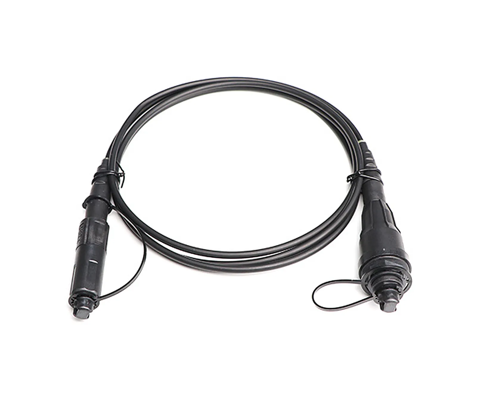
- Gender arrangement. The default is female-to-female, which is what "adapter" means in a catalog. A plug-in converter instead presents a male plug on one side and a female adapter on the other — used to retrofit an existing plug into a new interface. Both are sold as "adapters", and the difference is visible in the photograph, not in the name.
- Hybrid / conversion. Different interfaces on each side (SC to LC, LC to ST, FC to SC). Because the two sides hold different ferrule diameters, the conversion is a designed optical assembly rather than a sleeve swap.
- Shuttered. An internal or external shutter that closes when the plug is removed, shielding the laser light that would otherwise leave the open port.
- Bare fiber adapter. A test-bench part that temporarily holds a bare fiber in front of a detector or light source; it appears in equipment racks and labs, never in a link.
The LC-or-SC choice does not belong to the adapter: the adapter follows the plug, and the plug follows the transceiver. If that decision is still open, the cluster's LC vs SC comparison covers size, density and field handling.
The alignment sleeve: the only part inside an adapter doing optical work
Inside every adapter sits a sleeve, and the two ferrules press into it from opposite ends. Most sleeves are ceramic tubes with a split along their length; the split lets the sleeve flex slightly and grip each ferrule evenly. Single-mode fiber has a 125 µm cladding, so the sleeve's bore and its concentricity are what place two 9 µm cores on the same axis — the entire optical function of the adapter happens in that grip, not in the housing.
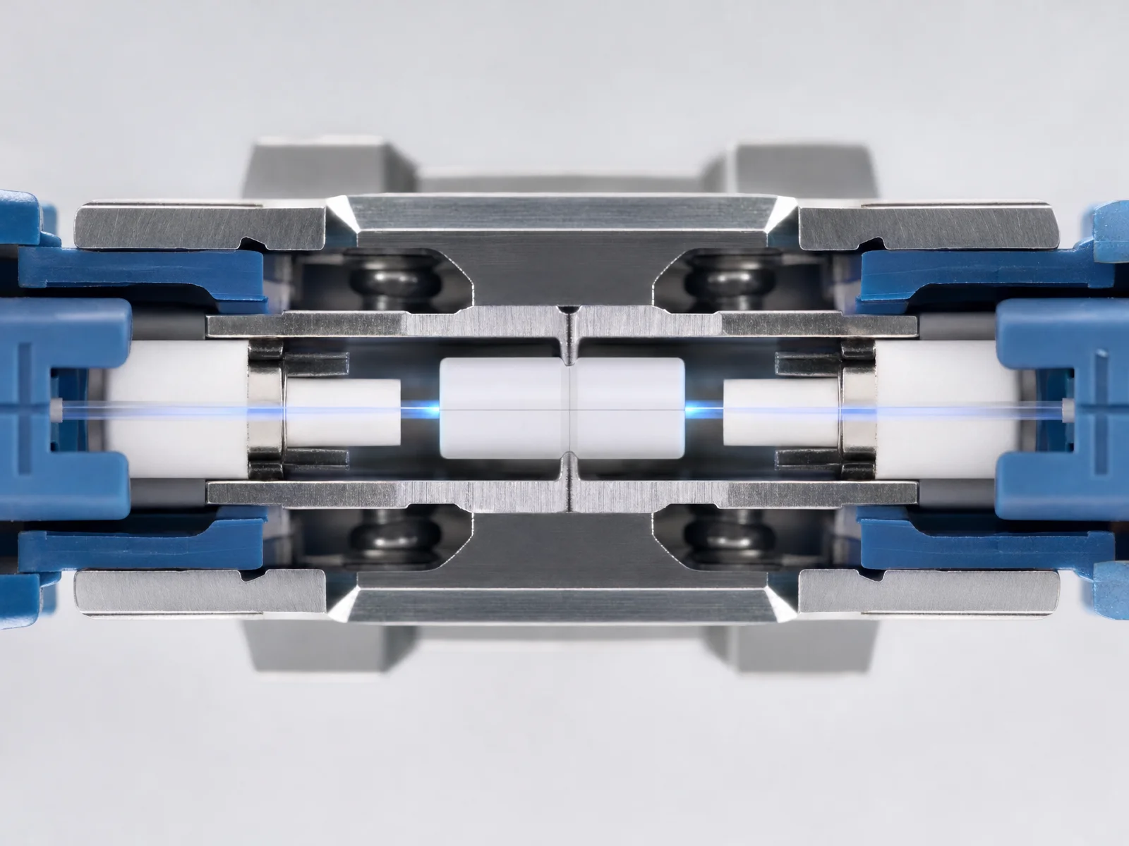
Sleeve material is the specification that separates a premium adapter from a low-cost one, and it is the specification most often left off a requisition. Zirconia ceramic is hard, dimensionally stable and the default for single-mode work; metal sleeves (phosphor bronze, sometimes stainless) are softer, opaque and cheaper, and are common in multimode and cost-driven consumer assemblies. The published adapter specification of a major connector manufacturer tests them as follows:
Parameter (SC / FC / ST adapters) | Zirconia sleeve, typical / max | Metal sleeve, typical / max |
|---|---|---|
Insertion loss | 0.05 dB / 0.20 dB | 0.10 dB / 0.30 dB |
Sleeve / ferrule withdraw force | 200 gf – 600 gf | 200 gf – 600 gf |
Operating temperature | −40 °C to +75 °C | −40 °C to +75 °C |
Durability | < 0.1 dB typical change over 500 matings | < 0.1 dB typical change over 500 matings |
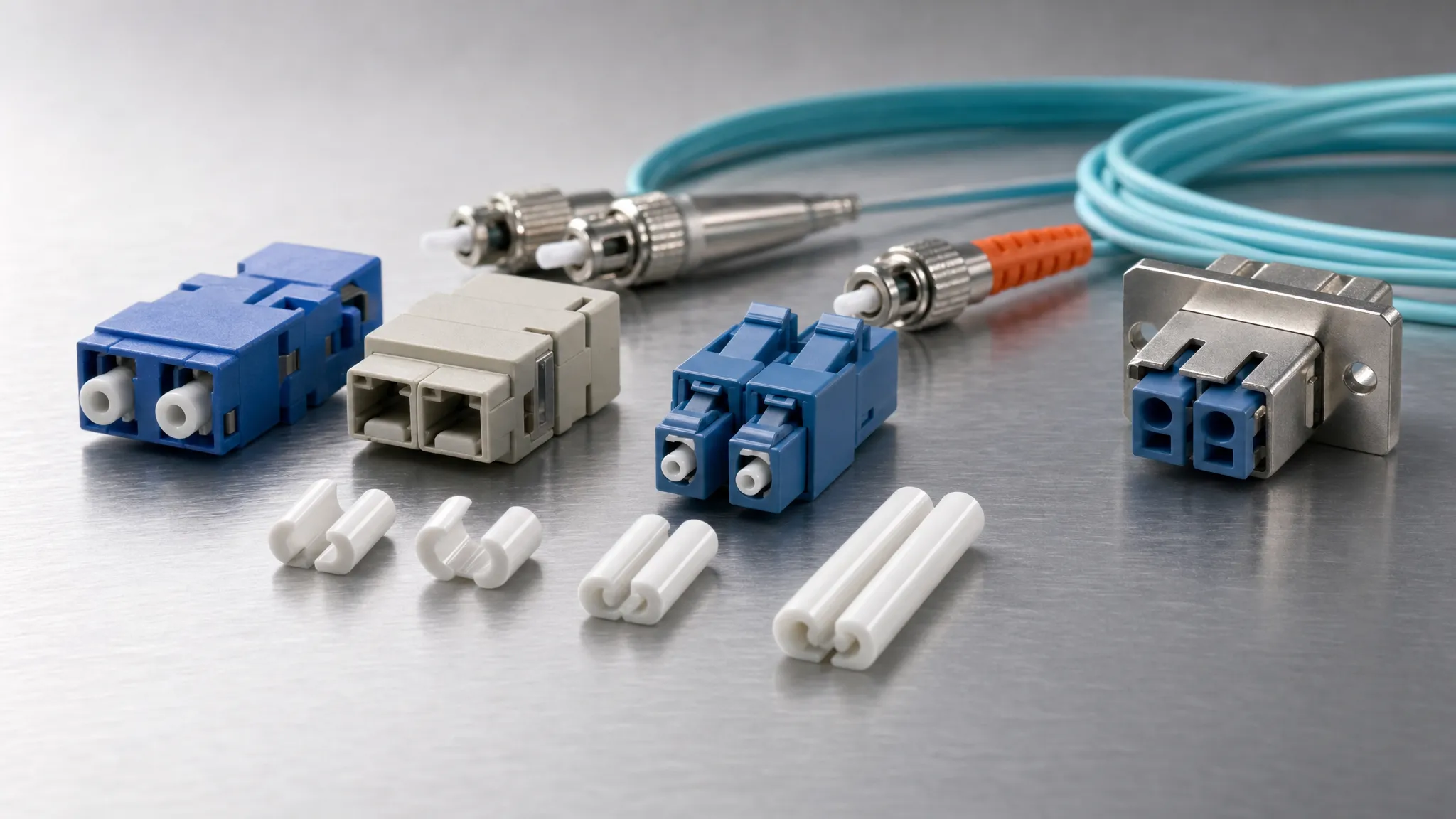
Read the footnote before you compare the two columns: in that published table the zirconia sleeve was tested with single-mode fiber and the metal sleeve with multimode — so 0.05 dB versus 0.10 dB is indicative of the class, not a like-for-like measurement. The stronger reading is the durability line: an adapter is rated for hundreds of mating cycles with a fraction of a dB of drift, which is why the connector wears out long before the adapter does. Sleeve material and adapter color are the two parameters to look for in a supplier's written specification — as on these cassette adapters with pre-installed zirconia sleeves.
That is also why the sleeve is the part you replace. Three failure modes show up in the field, all of them in the sleeve rather than in the housing:
- Contamination. Grit, dust or a dried film of cleaner on the inner bore scores the sleeve and the ferrule on every insertion. This is the most common cause of "this panel is bad" — and the reason a failed port is often fixed by cleaning plus a new adapter instead of new patch cords.
- Wear and ovality. Thousands of insertions, or repeated insertions of a dirty ferrule, open the sleeve's grip. The complaint is an insertion loss that creeps up on the same port while every patch cord passes on a different one.
- Cracked or splayed sleeve. Usually the result of forcing a ferrule in at an angle, or of a sleeve damaged by a misaligned plug-in converter. The port reads high loss or completely open.
Because the sleeve is captive in a low-cost housing, the practical maintenance answer is to keep a small bag of adapters and swap the whole part. What is not interchangeable is the sleeve inside a sealed or hardened interface: once an adapter is potted into an IP-rated body, replacing the part is the repair.
The other half of the alignment problem lives on the connector: the ferrule's bore, concentricity and endface geometry. That is covered separately in the cluster's guide to connector ferrules and their tolerances — the adapter aligns two ferrules, it does not correct a bad one.
Polish and color: UPC blue, APC green, and why they never mix
Single-mode connectors are polished two ways, and the adapter world encodes the difference in color. UPC (ultra physical contact) is a rounded, near-flat endface with return loss of 50 dB or better, usually blue; APC (angled physical contact) is an 8° angled endface with return loss of 60 dB or better, universally green. The angle exists to deflect the small reflection away from the laser rather than back into it, which is why PON access networks, RF-video overlay and any high-reflection-sensitivity link standardize on APC.
The rule that matters: APC and UPC must never be mated. The endfaces are physically incompatible — a flat ferrule cannot seat against an angled one — and forcing them together damages both endfaces and can push reflected power back toward the transmitter. Color is your field check, and it survives into sealed hardware, where a green insert inside a black bulkhead adapter is the only visible signal that the port expects APC.
Function / fiber | Adapter and sleeve holder color |
|---|---|
Single-mode, PC/UPC | Blue |
Single-mode, APC | Green |
Multimode, PC (62.5 µm and 50 µm) | Beige |
Multimode, laser-optimized OM3 | Aqua |
Multimode adapters are color-coded too — beige for legacy 62.5/50 µm, aqua for OM3 — and panel hardware is often supplied with a color-coded dust cap on the sleeve holder so that the correct adapter is used for the correct application, which is a manufacturing decision with a field consequence: a mixed-color panel is a mixed-application panel.
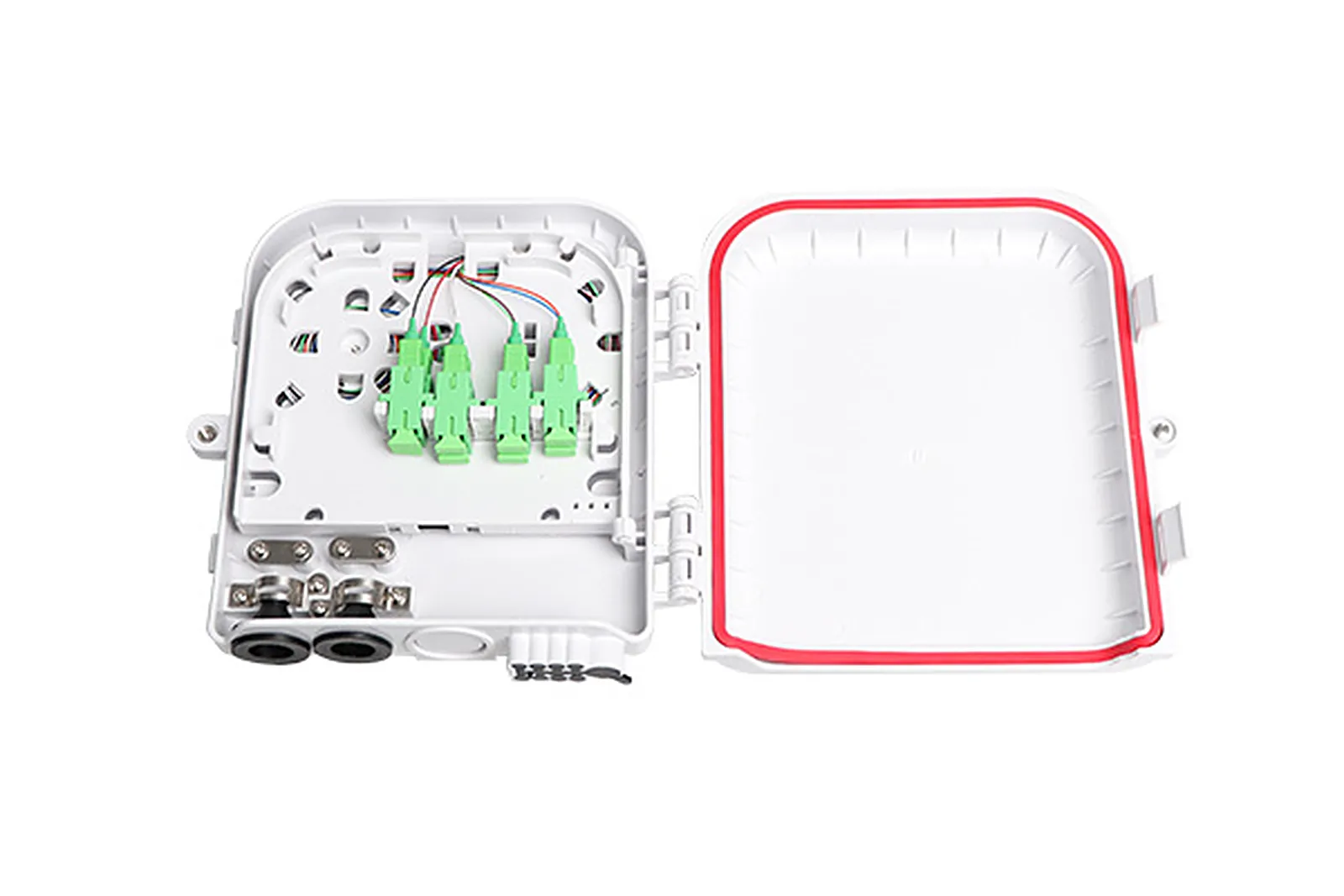
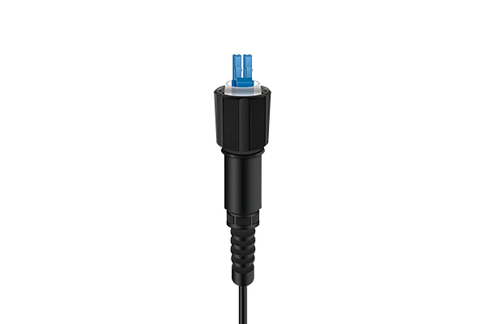
Two photographs, one rule. Inside the terminal box, every adapter is green because every port is APC; on the sealed outdoor assembly, the duplex LC plug is blue because the link is UPC. Swap either part and the port stops working — not because the housing will not fit, but because the endfaces will. If your BOM does not yet distinguish UPC from APC per port, the cluster's APC vs UPC comparison covers the return-loss arithmetic and the decision path.
What an adapter adds to a loss budget
The honest accounting is the one the FOA uses in its loss budget guidance: you count connections, not connectors, and every adapter is exactly one connection. A patch panel with two adapters adds two connections to the link, whether or not any fiber was spliced there. That single sentence resolves most budget arguments, because it stops people from counting an adapter as a component with its own loss and a connector as something with none.
Published planning values are broad enough to cover the spread between a carefully mated premium adapter and a cheap one:
Element | Typical measured | Value to plan with |
|---|---|---|
Mated connection, single-mode, factory-terminated plugs | 0.1 – 0.2 dB | 0.3 dB typical, 0.5 dB when you want margin |
Mated connection, multimode plugs | 0.2 – 0.5 dB | 0.75 dB (the EIA/TIA-568 maximum acceptable value) |
Adapter only, per the vendor spec table above | 0.05 dB typical (zirconia) | 0.20 dB maximum |
The reason to carry both columns is that a datasheet's "adapter insertion loss" is a statement about a connection — the adapter plus the two plugs that were in it during the test. Budgets therefore work better when you treat each adapter as a connection at 0.3–0.5 dB single-mode or 0.5–0.75 dB multimode, and stop trying to separate the adapter's share. Return loss behaves differently: it is a property of the mated endface pair, so an APC port can be degraded by the wrong polish on the plug even in a perfectly good adapter. If you are reconciling a measured link against a design, the cluster covers insertion loss versus return loss and the data-center cluster works through the same arithmetic for high-fiber-count links.
Two consequences follow. Mating durability is a budget item over time, not a datasheet footnote — a port rated for hundreds of cycles with under 0.1 dB of drift stays inside the budget for years; an out-of-spec sleeve does not. And an adapter cannot fix a loss it did not create: on a high port, the sleeve, the endfaces and the cleaning discipline are three separate suspects, in that order of likelihood.
Mounting and environment: flange, bulkhead, keystone, shuttered
The same mating sleeve is offered in a handful of mounting styles, and the mounting style is what makes an adapter a panel part.
Mounting style | What it is | Where it belongs |
|---|---|---|
Flange (panel-mount) | Adapter body with a flange and screw holes; simplex or duplex, rectangular or square cutout | Racks, ODF, patch panels, wall boxes |
No-flange (snap-in) | Retained by the panel's own clip, no screws | Dense panels, cassettes and adapter plates |
Bulkhead | Sealed, threaded or bayonet body that passes through an enclosure wall | Outside plant, FTTA radio heads, industrial enclosures |
Keystone | Adapter module sized for a standard wall-outlet or patch-panel keystone opening | Enterprise outlets, small distribution points |
Pre-terminated drop hardware | Male plug and female receptacle pair that replaces the adapter entirely | FTTH drops where speed of deployment dominates |
Flange and no-flange versions carry the same optical core; the difference is installation labor and cutout tolerance. A fiber optic adapter flange is therefore a purchasing decision, not a mounting detail: it decides whether the panel is machined and screwed or clipped. Panel cutouts need to be checked against the adapter's own footprint rather than inferred from the port count, because the SC footprint, the LC duplex footprint and the keystone cutout are three different openings. The MPO adapter adds a mechanical question that the other families do not have: it exists in opposed-keyway and aligned-keyway configurations, and with angled interfaces the keyway choice determines whether two down-angled plugs or one down-angled plus one up-angled plug are joined — get it backwards and polarity and angle pairing both break. The standard also caps the plug-to-adapter mating and unmating force at 30 N, which is why a stiff MPO adapter is a specification problem rather than a technique problem.
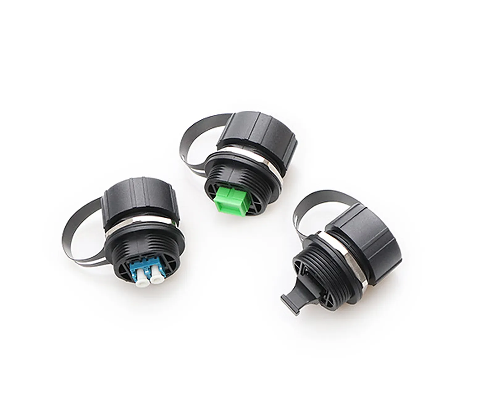
Outdoors, the adapter is usually the interface that must be sealed. An IP68 hardened adapter or receptacle is not a standard coupler in a rubber boot: the optical interface inside it is still the standardized one, which is why an industrial-LC assembly specified to IEC 61076-3-106 remains intermatable with other industrial-LC adapters and holds its optical spec from −40 °C to +85 °C across rain, salt mist and dust. The color code survives that transition, and it becomes the only way to tell an APC port from a UPC port behind a sealed cap. For the sealing grades themselves, the FTTA cluster's IP67 vs IP68 guide for outdoor connectors explains what each rating does and does not promise.
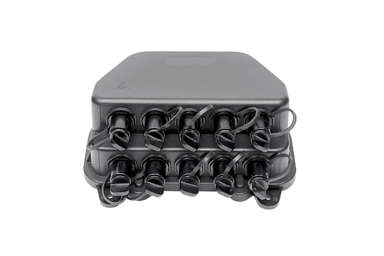
Dust caps are part of the specification, not packaging. Every adapter on the panel should be capped until a plug goes in, and caps should be tethered or bagged rather than loose — a dropped cap is how dust reaches a sleeve. If an adapter is going to sit in an open port for a long time, specify the shuttered version: the shutter closes on removal and shields the port from both contamination and the laser light leaving the ferrule. That last point is a safety requirement in its own right.
Eye safety, stated plainly: never look into a fiber endface, a ferrule, or an open adapter port. Laser light exiting a fiber is invisible at the wavelengths used in telecom links and will not trigger the blink reflex. Confirm a fiber is dark with a power meter before you inspect anything visually, and treat a visual fault locator as what it is — a visible laser. On the bench, clean in this order: a dry clean first, then a wet clean with 99% isopropyl alcohol, then inspect, clean again if the inspection shows residue, and inspect once more before you mate the connector.
Choosing a fiber optic adapter: a selection matrix
Selection collapses once the interface is fixed, because the interface determines the sleeve, the cutout and the panel arithmetic. Work in this order:
Decision | Question to answer | What it forces |
|---|---|---|
| Which connector is on the end of the fiber? | Ferrule size, retention, panel cutout; IEC 61754 part |
| UPC or APC? Single-mode or multimode? | Adapter color, sleeve type, and whether the port may mate a given plug |
| Simplex, duplex, or multi-port module? | Panel opening count and density |
| Flanged, no-flange, bulkhead, keystone? | Panel machining, screws vs clips, sealing |
| Rack, wall box, cabinet, outdoor enclosure? | IP rating, material, temperature range, shutter |
| Ports per panel × panels per rack unit | Purchase quantity and packing (kits vs bulk) |
The arithmetic in step 6 is where panels are usually mis-specified: a 1U panel that accepts four adapter plates or MPO cassettes at up to 144 fibers in a single rack unit is a density decision made at the panel level, and the adapter count follows from it directly. If the panel is the thing being bought, the data-center cluster's patch panel guide is the closer reference — this page only covers what goes into the openings.
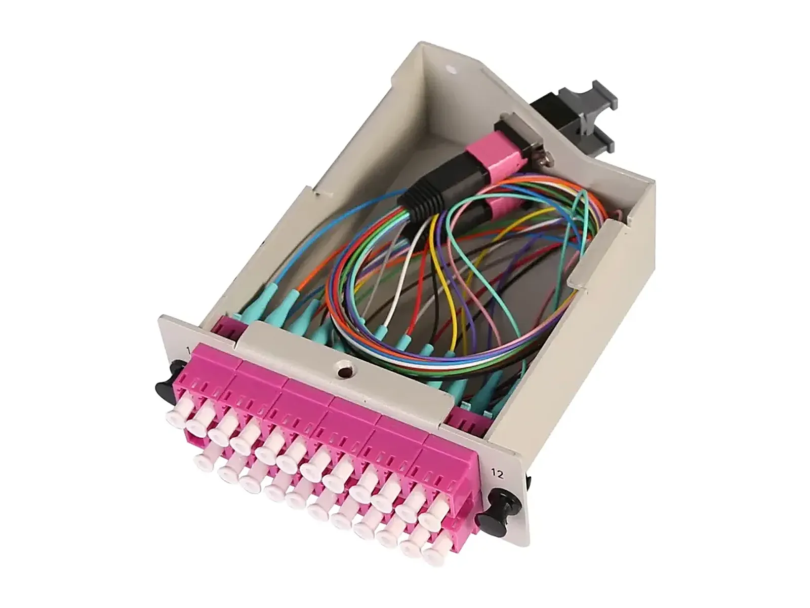
Kits exist for field work, and a fiber optic adapter kit is usually the cheapest way to cover a mixed panel: a labeled case of mixed interfaces, polish colors and mounting styles costs less than three line items and much less than a second truck roll. A kit is not a substitute for a part number — a bulk bag of "SC adapters" that turns out to be multimode beige on a single-mode blue panel is a return, not a saving.
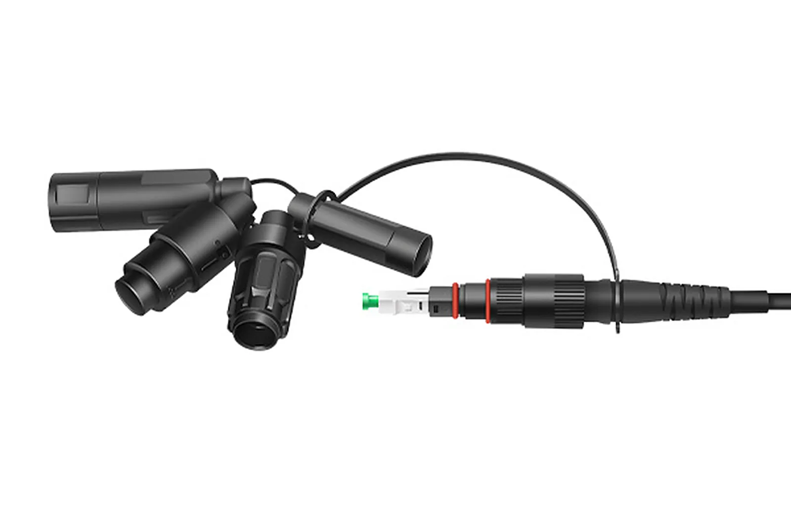
The last axis is not in the adapter at all: in pre-terminated FTTH and FTTA work, the "adapter" is often the network's chosen receptacle standard, so you match the connector to it rather than deciding it at the pole. A single universal SC assembly can be built to mate with four different outside-plant adapter standards, which is efficient at the depot and a trap at the site — the adapter standard is decided by the operator, so it belongs in the project documents before the material order, not in the installer's judgment at the pole. DYS builds these hardened interfaces as part of its outside-plant range, including assemblies that stay intermatable with industrial-LC adapters to IEC 61076-3-106 and hold their optical specification from −40 °C to +85 °C.
Incoming inspection and field care
An adapter is cheap enough that nobody wants to inspect it, and that is exactly why failures reach the panel. Five checks cover a delivery without a lab:
- Confirm the interface and the polish color, port by port. Blue, green, beige and aqua are the four you will see; a mixed box is a mis-picked order, and a wrong polish is a damaged link waiting to happen.
- Check the sleeve by eye and by feel. Look into the port: the ceramic sleeve should be clean, straight and undamaged, with the split visible. A cracked, splayed or discolored sleeve is a reject, not a bench fix.
- Verify the ferrule grip. A ferrule inserted into a good zirconia sleeve meets a consistent, firm spring resistance and withdraws with a perceptible drag — published adapter specs put that withdraw force at roughly 200–600 gf. A sleeve that swallows a ferrule loosely will read high insertion loss no matter which plug you use.
- Spot-check insertion loss and return loss on a sample, not on every piece. One reference cord, a light source and a power meter will do; the cheap adapter is the one that fails the sample, and the sample is what tells you whether the batch was a mistake.
- Check the mechanicals that the panel will see: flange square and flat, hinge or shutter closing fully, retention clip present, and a dust cap on every port that is not yet populated.
None of these checks proves reliability over time, so the last question is about evidence rather than the part: what the factory tests before shipment, on what equipment, and whether a report can be requested per batch. In DYS's own assembly lines, 100% of product is tested before shipment under a TL 9000 and ISO 9001 quality system, the reliability lab runs automatic insertion and extraction force testing and a 3D interferometer, and test methods follow GR-326 for connector reliability — the same parameters as the checks above. The outdoor assemblies themselves declare GR-1320, IEC 61753-1 and IEC 61754-4, so the environmental and interface performance is stated against a standard rather than a marketing claim.
For the maintenance side, the rule that pays for itself is to inspect before you mate and clean before you store, and to replace the adapter when a port fails rather than the patch cords. A port that has been cleaned twice and still reads high has a worn sleeve. Where to take the measurement, and with which instrument, is covered in the installation cluster's guide to testing fiber optic cable.
FAQ: adapter and coupler questions engineers actually ask
What is the difference between a fiber coupler and a fiber adapter?
In the trade, "coupler" is a synonym for a female-to-female mating adapter — the part that joins two connectors. In optical engineering, a fiber coupler is a different device: one or more input fibers and one or several output fibers, usually made by fusing fibers so their cores touch, and used as a splitter or as a WDM multiplexer. Both names exist because a mating adapter genuinely does couple two fibers together; only the fused device splits or combines light. If you are buying a patch-panel part, you want the adapter. If you are dividing one PON feed among subscribers, you want a splitter.
Is an adapter the same as a connector?
No. A connector terminates a fiber — it holds the ferrule, the spring and the latch, and it is the part polished onto the end of the cable. An adapter terminates nothing; it is a socket that holds two connectors in alignment. Connectors are purchased with cable or pigtails; adapters are purchased for panels and enclosures.
Do I need a special adapter for APC?
Yes, in the sense that the adapter's color and sleeve holder must match the polish: green for APC, blue for PC/UPC, beige and aqua for multimode. The mechanical interface is the same, which is precisely the danger — an APC plug will physically enter a UPC adapter, and forcing it damages both endfaces. Never mix the two.
How many mating cycles does an adapter last?
Published adapter specifications rate the class at several hundred cycles with less than 0.1 dB of typical change — 500 matings is a common figure — and the number is dominated by cleanliness rather than by the sleeve material. What ends an adapter's life early is contamination: a dirty ferrule acts like grinding paste on the bore, so a port that is cleaned and re-mated constantly will outlast one that is mated occasionally with dirty plugs.
Can I replace just the alignment sleeve?
In an open panel-mount adapter, the sleeve is a captive part and the practical repair is to replace the adapter. In a sealed or hardened interface the sleeve sits inside a potted body, so the whole part is the replacement unit. Either way, keep the interface, polish color and mounting style identical so the port is not re-keyed.
Do I need shuttered adapters?
For any port that is open while the laser is live — equipment ports, ports awaiting a jumper, high-density panels that are populated incrementally — a shutter shields both the light and the sleeve. For ports that stay populated, a plain adapter with a dust cap is sufficient.
Bottom line
A fiber optic adapter is not a passive accessory; it is the component that decides whether two connectors actually meet. Fix the interface, fix the polish color, confirm the sleeve material and the mounting style, count each adapter as one connection in the loss budget, and inspect on receipt with the five checks above. That is a defensible specification for a part that costs a few dollars and can cost a network a great deal more.
DYS Fiber Optic manufactures the connector and adapter-adjacent hardware that goes into these panels and enclosures — pre-terminated FTTH and FTTA assemblies, sealed outdoor interfaces and MPO/MTP cabling — for telecom operators, ISPs and data-center builders. If you are specifying adapters, panels or hardened receptacles for a deployment, you can see the FTTH cabling range and the MPO/MTP data-center range, or send the drawing and the port list and we will quote against it.