

Data Center
Fiber Patch Panel Guide: Types, Density, and Selection
A fiber patch panel is the enclosure where a multi-fiber cable is terminated, organized, and connected to patch cords — the point in the rack where fiber becomes manageable. Choosing one is not a catalog browse: four numbers (fiber count, connector type, rack-unit budget, termination method) narrow every project to a single panel family. This guide walks through the fiber patch panel types you will actually see in racks, the density math that decides 1U versus 2U, and a step-by-step selection process you can run against your own switch and cable counts. It is written from inside the trade: DYS Fiber Optic has manufactured fiber patch panels for data centers since 2009, and added MPO/MTP cassette and pre-terminated assembly capability when it built out its MPO line in 2014.
What a fiber patch panel does — and the four specs that define one
A patch panel terminates incoming fiber, presents the connections on front-facing ports, and protects the splices and slack behind them. Its point is not the metal box — it is that every fiber in the building ends at a labeled, testable, re-patchable port instead of dangling inside a cabinet. That is also the answer to the common question "what is the point of a patch panel": it converts a permanently installed cable plant into a flexible cross-connect you can rearrange without touching the trunk.
A fiber patch panel and a fiber enclosure are different things, and the terms get blurred. A panel is a rack-mount unit built for termination and patching — adapter plates or cassettes on the front, splice trays and slack storage behind. An enclosure (often called an ODF or distribution box) is a wall-mount or outdoor cabinet that does the same job at a smaller scale, usually with fewer fibers and without rack mounting. If it goes in a 19" rack, it is a panel; if it bolts to a wall or a pole, it is an enclosure.
Behind every panel purchase are four specs that define the product:
- Fiber count — how many fibers must be terminated now, plus the growth you are willing to pay for. Bulk cables bundle fibers in groups of 12, so realistic counts are 12, 24, 48, 96, and 144.
- Connector type — LC duplex for most switch ports, SC for single-fiber legacy links, MPO for parallel optics. The adapter plates or cassettes must match what your patch cords and trunks use.
- Rack-unit budget — how much vertical space the panel may occupy. One rack unit (1U) is 44.45 mm, and density is measured in fibers per RU.
- Termination method — fusion-spliced pigtails in splice trays, direct connectorization, or factory pre-terminated trunks. This decides whether the panel needs splice capacity at all.
The jacket of an incoming cable usually tells you the first number: the print legend lists fiber count and mode, and TIA-598 fiber color coding lets a technician read mode and fiber position from the jacket colors before the cable is opened. Everything downstream — which adapters, how many splice trays, which cassettes — follows from these four numbers. For the broader picture of how panels sit inside a full cabling architecture, our data center fiber cabling guide covers MPO/MTP systems, loss budgets, and the migration path from 100G to 400G/800G.
Fiber patch panel types: mounting, format, and connector options
Manufacturers sort panels along three axes — mounting, format, and connector — and most of the "types" lists you will see are combinations of the three.
Dimension | Options | Typical use |
|---|---|---|
Mounting | Rack mount (19"/23"), wall mount, outdoor/NEMA, DIN rail | Rack mount dominates data centers; wall mount suits edge closets; outdoor units protect splices at OSP handoff points |
Format | Fixed, sliding tray, drawer/rotary | Fixed is cheapest; sliding and drawer trays pull out for front access to splices and slack |
Connector | LC, SC, ST, FC, MPO/MTP | LC for high-density switch patching, SC for singlemode trunks, MPO for parallel optics |
Load state | Unloaded (blank), loaded with adapters, loaded with adapters + pigtails | Unloaded lets you grow; loaded ships ready to terminate |
Termination | Patch-only, splice-and-patch | Splice-and-patch panels carry splice trays for fusion-spliced pigtails |
A rack mount fiber patch panel is the default in any data center or telecom room: it mounts on the standard 19" rails, occupies 1U or 2U, and fronts LC, SC, or MPO ports. A wall mount fiber patch panel is the same function in a compact box for sites where there is no rack — remote cabinets, small offices, and MDU telecom rooms. Outdoor panels add a NEMA-rated enclosure for weather protection, and DIN-mount panels clip onto DIN rails inside industrial control cabinets.
Within rack-mount panels the format decision matters more than it looks. Fixed panels are a single stamped chassis — cheap, rigid, and fine when you rarely touch the back. Sliding-tray panels pull out of the rack so a technician can reach splice trays and slack without unracking the unit. Drawer and rotary formats push the same idea further for ultra-high-density installations where rear access is impossible. If your splices live inside the panel (they usually do), sliding access is worth the few extra dollars.
On the connector axis, LC is the workhorse: duplex LC adapters give two fibers per port, and a standard 1U panel holds 24 to 48 duplex adapters — 48 to 96 fibers per rack unit. SC panels still appear where singlemode trunks terminate, and ST/FC survive in legacy plants. MPO/MTP panels are the high-density answer: they front multi-fiber ferrules instead of individual connectors, which is how panels reach 144 fibers in a single RU.
Density math: how many fibers fit in your rack
Density is the number that most buyers get wrong, because they think in ports when they should think in fibers. Every port consumes fiber: a duplex LC port uses 2, an MPO-12 port uses 12 (8 in practice on 4×100G links), an MPO-16 port uses 16. Multiply ports by fibers per port, and you have the real number the panel must terminate.
The math runs on two facts. First, a rack unit is 44.45 mm (1.75 in), defined by the EIA-310 standard for 19-inch racks. Second, fiber-per-RU is the honest density metric: a 1U LC panel with 24 duplex adapters terminates 48 fibers; a 1U high-density LC panel with 48 duplex adapters terminates 96; an MPO panel with four 12-fiber adapter plates terminates 144. The table below is the short version.
Panel | Connectors | Fibers per 1U | Best for |
|---|---|---|---|
24-port LC (unloaded or loaded) | 24 duplex LC | 48 | Small closets, campus links, low fiber counts |
48-port LC | 48 duplex LC | 96 | Enterprise data centers, leaf rows |
MPO-12 panel (4 plates × 3 adapters) | 12 MPO-12 ports | 144 | High-density cores, 100G/400G SR4, pre-terminated trunks |
MPO-16/MPO-24 panel | 8 MPO-16 or 12 MPO-24 ports | 128–288 | 800G DR8/FR8 migration, hyperscale rows |
A worked example makes the trade visible. Say a leaf row has 12 switches, each with four 100G uplinks, and each uplink runs on 8 fibers (4×100G SR4 over MPO-12). That is 12 × 4 × 8 = 384 fibers. Terminated on 48-fiber LC panels, the row eats 8 RU of panels. Terminated on 144-fiber MPO panels, the same 384 fibers eat 2.7 RU — a saving of more than 5 rack units per row, at the cost of MPO trunks, cassettes, and the polarity discipline they demand.
The 400G-era rule of thumb: the higher the line rate, the more parallel lanes, and the faster you should plan MPO panels even if today's ports are still LC. IEEE 802.3bs, the 400G Ethernet amendment, is the standard that pushed 8-fiber and 16-fiber parallel links into mainstream switch ports — the full picture of that migration is in our guide to 400G/800G data center cabling.
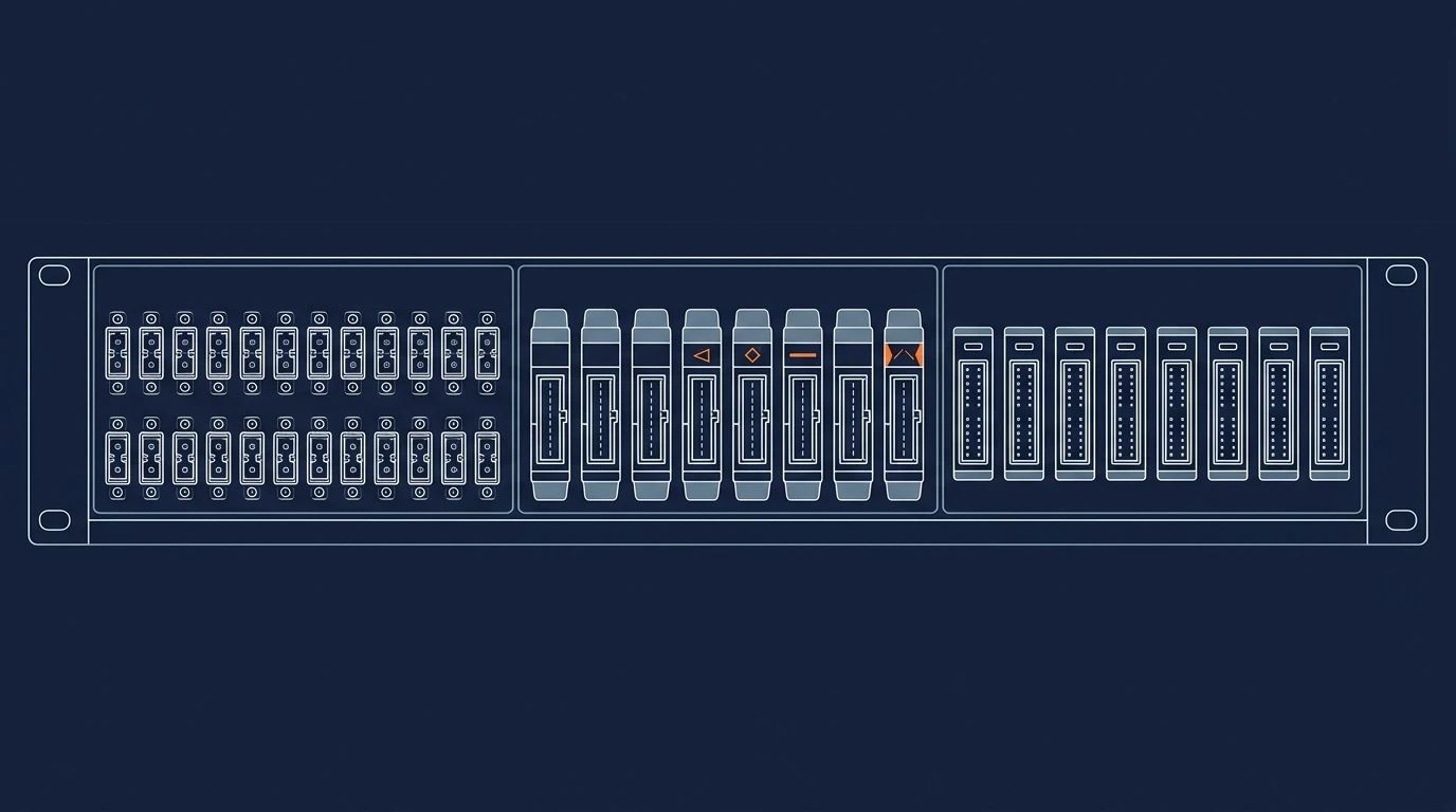
Figure: the same rack unit terminates 48 fibers with LC duplex, 144 with MPO-12 plates, and more with MPO-16 — density is a connector decision as much as a panel decision.
One caveat before you max out every RU: density trades against access. A 144-fiber 1U panel with sliding tray still has tight finger space, and patching 48 duplex LCs into a dense panel is slower than patching into a 2U with room to breathe. If your team patches constantly, prefer 96 fibers per 1U with a sliding tray over 144 in a fixed chassis. If the panel connects trunks that rarely change — spine-to-leaf MPO links, for example — 144 per RU is the right call. This is the density-versus-maintainability judgment that no spec sheet makes for you.
MPO cassettes vs LC adapter plates: which belongs in your panel
Given a panel chassis, the front-end choice is between adapter plates and cassettes — and it changes how the panel is cabled. Adapter plates are stamped metal or polymer fronts holding bare adapters; fibers are terminated at the adapter rear, typically by splicing pigtails. Cassettes are sealed modules that convert one or two MPO ports on the rear into a bank of duplex LC ports on the front, with the internal fiber routing factory-made and tested.
Decision | Adapter plate | MPO cassette |
|---|---|---|
Rear connection | Spliced pigtails or direct termination | Factory-terminated MPO trunk plugs in directly |
Front ports | Whatever adapters the plate holds | LC duplex (typically 6 or 12 per cassette) |
Insertion loss | Depends on field splices + adapter pair | Factory-controlled, lower and more consistent |
Best when | Small counts, existing LC plant, tight budget | Trunk-to-switch patching, high density, 400G/800G |
Change cost | Re-terminate or re-splice to change | Swap the cassette, trunk stays untouched |
The rule is simple: if the cable behind the panel is an MPO trunk, use cassettes — the trunk plugs into the cassette rear, the cassette converts to LC for the switch ports, and no field splicing happens in the panel. If the cable is a conventional breakout or distribution cable with individual fibers, adapter plates with spliced pigtails are the conventional, lower-cost path. Cassettes also win where insertion loss matters most: the factory-made internal routing in a cassette is tested once and holds a tighter loss spec than a field splice, which is exactly the margin that counts at 400G and above.
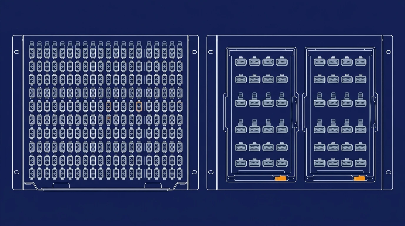
Figure: both front ends mount in the same 1U chassis — the difference is what plugs into the rear.
Cassettes introduce one question adapter plates never ask: MPO polarity. A cassette is a Type A, B, or C device, and the trunk's polarity method must match the cassettes at both ends or the link will not light. This is the single most common MPO panel install error, and it is worth reading the polarity explainer before you order cassettes in volume. Also note that "MPO" and "MTP" are not synonyms for the panel spec — MTP is US Conec's brand of the MPO connector, and the two are compatible but not identical, which matters for ferrule quality and float on high-density panels. When you source cassettes, specify the exact ferrule and polishing grade; our MPO cassettes are built in both standard and low-loss grades for power-budget-critical links.
How to choose a fiber patch panel for your racks, step by step
Run these five steps in order, and the panel picks itself. Keep a piece of paper: each step produces one number or one choice, and the five answers are your RFQ.
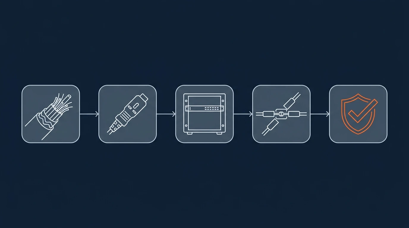
Figure: each step produces one number or one choice — fiber count, connector, density, termination, and panel spec — and the five answers form the RFQ.
Step 1 — Count the fibers, then add growth. Total the fibers behind the panel: trunk fiber count, or switch ports × fibers per port (2 for duplex LC, 8 for MPO-12 100G links, 16 for MPO-16 800G links). Add 20–30% growth if the panel must survive the next refresh cycle; leave at least 10% of ports dark. Round up to the nearest 12 — bulk cable and adapter plates are built in 12-fiber steps.
Step 2 — Fix the connector and polish. The panel's front must match your patch cords and switch side: LC/UPC for most multimode patching, LC/APC for singlemode PON-style links, MPO-12 or MPO-16 for parallel optics. Do not mix polish grades in one panel unless the plates are physically keyed to prevent mismating.
Step 3 — Choose density against access. Convert the fiber count to RU: 48 fibers per 1U on LC, 96 on high-density LC, 144 on MPO. Compare against your rack-unit budget. If the count fits in 1U of MPO but your technicians will re-patch it weekly, take 2U of LC instead — accessibility is a feature, not a luxury.
Step 4 — Decide termination. If the cable is fusion-spliced in the field, the panel needs splice trays (splice-and-patch format) and pigtails to the adapters. If the cable arrives pre-terminated, a patch-only panel — or a cassette panel with MPO rear ports — removes field splicing entirely. Pre-terminated trunks with panels are the fastest install path and the standard choice in new data center builds.
Step 5 — Verify the panel spec, then price it. Confirm the mechanicals against your rack: 19" or 23" mounting (rotatable ears cover both), powder-coated steel for a long finish life, sliding tray if splices live inside, and enough slack storage for the fiber count. Then price it — and here is what nobody lists on the spec sheet: cost scales with port count, connector type, and load state. An unloaded 1U chassis is the cheap base; loaded adapter plates cost more; MPO cassettes are the biggest line item, which is why the cassette-vs-plate decision in the previous section is also a budget decision. On standards: the TIA-568 series sets the performance baselines that panels, adapters, and patch cords are measured against, and a panel that meets TIA adapter-interface requirements will mate cleanly with any compliant cord. When you have the five answers, send them to a manufacturer rather than a distributor if volume or customization is involved — a factory can confirm the panel family, the cassette polarity, and the pre-terminated trunk lengths in one reply. As a reference point for what a built-for-density panel looks like, our HD series MPO/MTP patch panels take up to four adapter plates or cassettes in 1U — up to 144 fibers — with a sliding tray and rotatable 19"/23" ears.
Five mistakes that cost rack space and link budget
- Oversizing ports instead of fibers. Buying a 48-port panel "for growth" when the cable behind it carries 24 fibers wastes RU and leaves dead adapters. Size the panel to the cable, not to a round port number.
- Ignoring bend radius at the panel. Fibers enter the panel at the rear and bend into splice trays; a panel without proper slack routing forces tight bends. Use G.657 bend-insensitive fiber at the tail end of the plant, and confirm the panel's minimum bend radius matches your cable's rating.
- Forgetting cabinet door clearance. A sliding-tray panel is useless if the cabinet door closes 10 cm in front of it. Measure depth and door swing before choosing sliding, drawer, or rotary formats.
- Mixing polarity on MPO panels. Type A trunks with Type B cassettes, or key-up with key-down adapters, produces links that test fine at one end and dead at the other. Standardize the polarity method across trunks, cassettes, and panels before ordering.
- Buying loaded panels with no expansion path. A fully loaded panel is a dead end: every port is spoken for and there is no blank space. Prefer one blank plate per panel — the cost is a few dollars and the option value is a full upgrade path.
Bottom line: four numbers, one panel
Fiber count, connector type, rack-unit budget, and termination method — answer those four and the panel family is decided; the remaining choice is density versus maintainability, which is a judgment about your own patching habits, not a spec sheet. If you are planning a rack refresh or a new row, send the four numbers (plus your switch and trunk counts) to DYS Fiber Optic — our engineers will confirm the panel family, cassette polarity, and trunk lengths before you commit to a bill of materials.