

Data Center
MPO Polarity Explained: Types A, B, C & Flipped Links
MPO polarity is the mapping rule that keeps the transmit (Tx) fiber of every link aligned with the receive (Rx) fiber at the other end of an MPO-based connection. Get it wrong, and a cable plant that passed every loss test still refuses to carry traffic — the classic flipped-link failure. This guide explains MPO polarity types A, B, and C, how key-up and key-down connectors control it, how to test polarity before you trust a link, and how to keep polarity mistakes out of your purchase orders.
The short version:- Polarity is a system property. Trunk, cassettes, and patch cords must all follow one method (A, B, or C), or the link flips.- Type A maps straight through (key-up to key-down); Type B fully reverses the array (key-up to key-up) and is the parallel-optics default; Type C pair-flips and is legacy.- Flipped links pass loss tests. Verify polarity explicitly, at the factory and in the field.- Specify polarity, gender, and polish on every purchase-order line. The label is the documentation.
What Is MPO Polarity?
An MPO (multi-fiber push-on) connector carries multiple fibers in one ferrule — typically 8, 12, 16, or 24, up to 144 in trunk assemblies — which is why high-density data center fabrics use it. But a single connector interface multiplies the alignment problem: every one of those fibers has to land on the correct counterpart at the far end. In a duplex system, the transmitter and receiver roles are fixed per fiber. In a parallel MPO system, each fiber position has a defined role, and the mapping between positions on the two ends of every cable and patch cord must keep Tx connected to Rx across the whole link.
That end-to-end mapping is polarity. It is not a property of one cable; it is a property of the entire chain — trunk, cassettes, patch cords, adapters, and transceivers — and every component in that chain has to be ordered and verified against the same scheme. The industry framework for doing this is defined in the TIA-568 structured cabling standard (see the TIA/EIA-568 standard reference), which specifies three polarity methods, plus the IEC 61754-7 connector interface standard for the MPO family (IEC 61754-7 publication).
Why should a cabling engineer care? Because polarity failures are invisible to most test gear until a link is lit: insertion loss can measure fine while both ends transmit on the same fiber. The failure shows up as a link that never comes up, a channel that errors intermittently, or a transceiver pair that seems DOA. Diagnosing it after installation costs hours; specifying it correctly at ordering time costs a minute.
For the broader context of where MPO systems fit in a data center — fiber counts, loss budgets, and the 400G-to-800G migration — start from the Data Center Fiber Cabling Guide, the pillar this article belongs to. If you are still deciding between connector families, our MPO vs MTP connectors comparison covers the naming and mechanical differences.
The Three MPO Polarity Types: Type A, Type B, and Type C
TIA-568 defines three polarity methods — Method A, Method B, and Method C — and each method is realized with a matching cable type (Type A, Type B, or Type C). The "mpo polarity types a b c" distinction comes down to one thing: how fiber positions map from one end of the cable to the other, combined with the key orientation of the connectors.
- Type A (straight-through). The connector keys are opposite — key-up on one end, key-down on the other. Fiber position 1 at one end lands on position 1 at the far end, position 2 on position 2, and so on: a one-to-one mapping. Because nothing flips inside the cable, a duplex link built with Method A needs a crossed (A-to-A) duplex patch cord at one end to swap the Tx/Rx pair at the equipment.
- Type B (reversed). The connector keys are the same — key-up on both ends — and the fiber array is fully reversed: position 1 at one end lands on position 12 at the other, position 2 on position 11. The flip is built into the cable, which is why Type B is the workhorse of parallel optics: with straight (A-to-B) duplex patch cords on both ends, the reversal happens exactly once, in the trunk.
- Type C (pair-flipped). The keys are opposite like Type A, but adjacent pairs of fibers swap inside the cable: position 1 lands on position 2, position 2 on position 1, position 3 on position 4, and so on. Type C was designed for duplex backbone links where the flip happens inside the cable instead of in a patch cord. It does not support parallel optics — flipping pairs in an 8-fiber parallel link scrambles the lanes.
The table below summarizes the difference, because most polarity mistakes start with mixing up these three rows:
Polarity type | Fiber mapping | Key orientation | Typical use |
|---|---|---|---|
Type A | Straight-through (1→1, 2→2…) | Key-up to key-down | MPO-to-LC cassette links, structured cabling |
Type B | Fully reversed (1→12, 2→11…) | Key-up to key-up | Direct MPO-to-MPO parallel optics (40G/100G/400G SR4/DR4, 800G SR8) |
Type C | Pair-flipped (1↔2, 3↔4…) | Key-up to key-down | Duplex LC breakout backbones (legacy) |
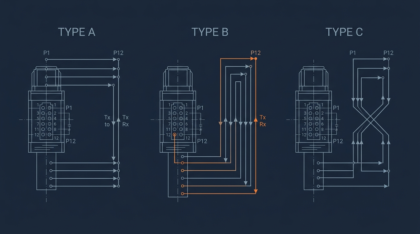
Figure 1: The three MPO polarity types in one picture — the fiber-position mapping is what makes them different, not the connector body.
Two terminology traps cause most of the confusion. First, "method" and "type" are not interchangeable: the method is the end-to-end connectivity scheme (how trunk, cassettes, and patch cords work together), while the type is the cable's own fiber mapping. You implement "mpo connector polarity method a b c" by choosing the matching cable type. Second, a Type B cable is often loosely called "reversed" — what actually reverses is the fiber order, and it reverses exactly once, which is why one Type B trunk replaces the crossed patch cord that Method A needs at the equipment end.
Which type dominates in practice? For parallel optics — the 40G/100G/400G SR4/DR4 links that most data centers run — Type B is the default choice, because a single key-up-to-key-up trunk with straight patch cords gives you the one reversal the link needs. Type A remains common in cassette-based structured cabling where the equipment side terminates in LC duplex. Type C has largely fallen out of new designs.
Key-Up vs Key-Down: How the Connector Key Controls Polarity
The "mpo polarity key-up key-down" question is really about the connector key: a raised ridge on the MPO housing that stops the connector from being inserted the wrong way. The key position — up or down — determines which fiber position mates with which position in the adapter, and therefore which mapping you actually get.
Think of it this way: an MPO ferrule is symmetrical in shape but not in fiber layout. If you could plug it in upside down, fiber position 1 would land where position 12 should be. The key prevents that — it forces one orientation. So a Type A cable carries key-up on one end and key-down on the other because the adapter between them (a standard key-up-to-key-down adapter) mirrors the connector, and that mirroring is what produces the straight-through mapping. A Type B cable carries key-up on both ends, and when two key-up connectors meet in a key-up-to-key-up adapter, the fiber order is reversed — which is exactly the reversal Type B wants.
The practical rule for the field: the adapter's keying must match the cable type you are installing. A Type A or Type C cable plugs into key-up-to-key-down adapters; a Type B cable plugs into key-up-to-key-up adapters. Mixing them up — plugging a Type B trunk into a standard adapter — forces one end to be inserted rotated, which bends ferrules, damages pins, and scrambles the mapping. When you see an MPO connector that will not seat without excessive force, check the keys before you check anything else.
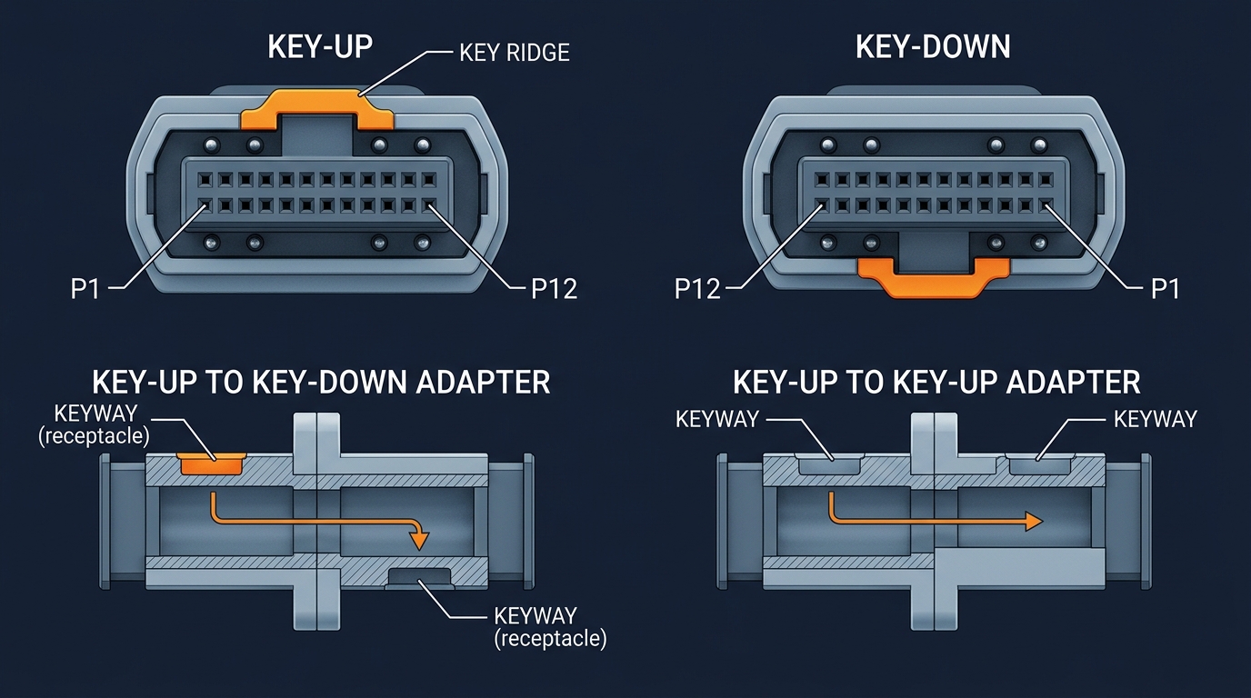
Figure 2: The key is the polarity mechanism — the same ferrule produces straight-through, reversed, or pair-flipped mapping depending on key orientation and adapter type.
One more orientation detail: single-mode MPO systems use APC (angled, 8°) end faces while multimode systems use UPC (flat). The key and the polish are independent, but an APC connector will never mate correctly with a UPC one — and unlike a polarity error, an APC/UPC mismatch is a physical loss disaster, not a logical one. Specify polish on every SKU alongside polarity, and put both on the label.
How Flipped Links Happen — and How to Diagnose Them
A "flipped link" is the failure mode you get when the end-to-end mapping is wrong: somewhere in the chain, a transmit path meets another transmit path instead of a receiver. It is the most common MPO deployment failure that is not a loss problem, and it tends to appear in exactly the situations where everything was tested.
The classic symptoms:
- The link never comes up, even though the transceiver is good and the insertion loss on every segment measures within budget.
- The link comes up but errors intermittently, often getting worse as temperature or traffic rises — a partial flip (one lane wrong) that the optics tolerate at low rates but not at line rate.
- A channel swaps roles: port A's transmit appears on port B's transmit, so a loopback test passes while a live link fails.
The root cause is almost always one of three things:
- Mixed polarity families in one chain — a Type A trunk with Type B cassettes, or a Type B trunk with Type A cassettes. Each component tested fine in isolation; the combination is wrong. This is the number-one cause and it is a documentation problem, not a hardware problem.
- The wrong duplex patch cord at the equipment end — Method A needs an A-to-A (crossed) patch cord at one end; installing an A-to-B (straight) cord silently un-flips the link.
- A mislabeled or mis-ordered assembly — the cable is marked Type B but was terminated Type A, or the wrong type was picked off the shelf at install time.
Diagnosis, in order:
- Read the labels first. Reconstruct the intended mapping: what type is the trunk, what type are the cassettes, what type are the patch cords at each end? If the chain does not follow one coherent method (per the TIA-568 framework), you have found the problem without touching a fiber.
- Verify polarity with a proper test (next section). A light-source-and-power-meter test with a fanout, or an MPO polarity tester, tells you the actual fiber-to-fiber mapping at each mated pair.
- Fix the mismatch, not the hardware. The cheapest fix is usually swapping a patch cord (A-to-A for A-to-B, or vice versa). If the mismatch is between trunk and cassettes, a polarity-conversion adapter can reconcile key-up-to-key-down and key-up-to-key-up — a standard accessory in MPO systems — or the cassette can be re-terminated. Only when the trunk itself is the wrong type (or mislabeled) do you need to replace it.
The broader point: flipped links are almost always a planning failure that surfaces at deployment.
A flipped link is almost always a planning failure that surfaces at deployment time — the hardware didn't change, the plan did.
The data center teams that avoid them are the ones that treat polarity as one decision made once for the whole plant, not as a per-cable attribute. We will come back to that in the ordering section.
MPO Polarity Testing: Verifying Before You Trust the Link
MPO polarity testing is a separate step from insertion-loss testing, and it needs to happen at two points: on the factory floor, and in the field after installation. Loss testing alone will not catch polarity errors — Fluke Networks' MPO testing guide makes exactly this point: MPO links need polarity verification because loss budgets at 40G and above are too tight to absorb a re-test cycle later.
Factory testing. Every pre-terminated MPO assembly should be tested for polarity, gender, polish, and insertion loss before it ships, with the results documented per cable. This is where the manufacturing process earns its keep: a factory that terminates and tests each assembly against the ordered mapping catches a flipped trunk before it ever reaches your rack. For a vertically integrated manufacturer this is a routine step — DYS Fiber Optic runs 100% IL/RL testing on MPO/MTP assemblies before shipment, backed by its TL 9000 quality system, and ships test data with serial-number traceability on request. The point of mentioning it here: when you receive MPO cables, the test report should show polarity mapping per fiber, not just total loss.
Field testing. Two approaches, depending on what you own:
- Light source + power meter with MPO fan-out cords. You connect the source to one fiber position at end A and check for light at the expected position at end B, then step through each fiber. It is slow — one fiber pair at a time — and error-prone, but it works with gear you already have, and an MPO fan-out patch cord turns any duplex tester into a per-fiber polarity checker.
- MPO polarity tester or multifiber test set. Purpose-built testers (for example Fluke's MultiFiber Pro class of instruments) test all fibers simultaneously, report the mapping, and flag any position that does not match the expected type. One pass tells you whether the link is Type A, B, or C and whether it matches the design. If you certify links for a living, this pays for itself in one large deployment.
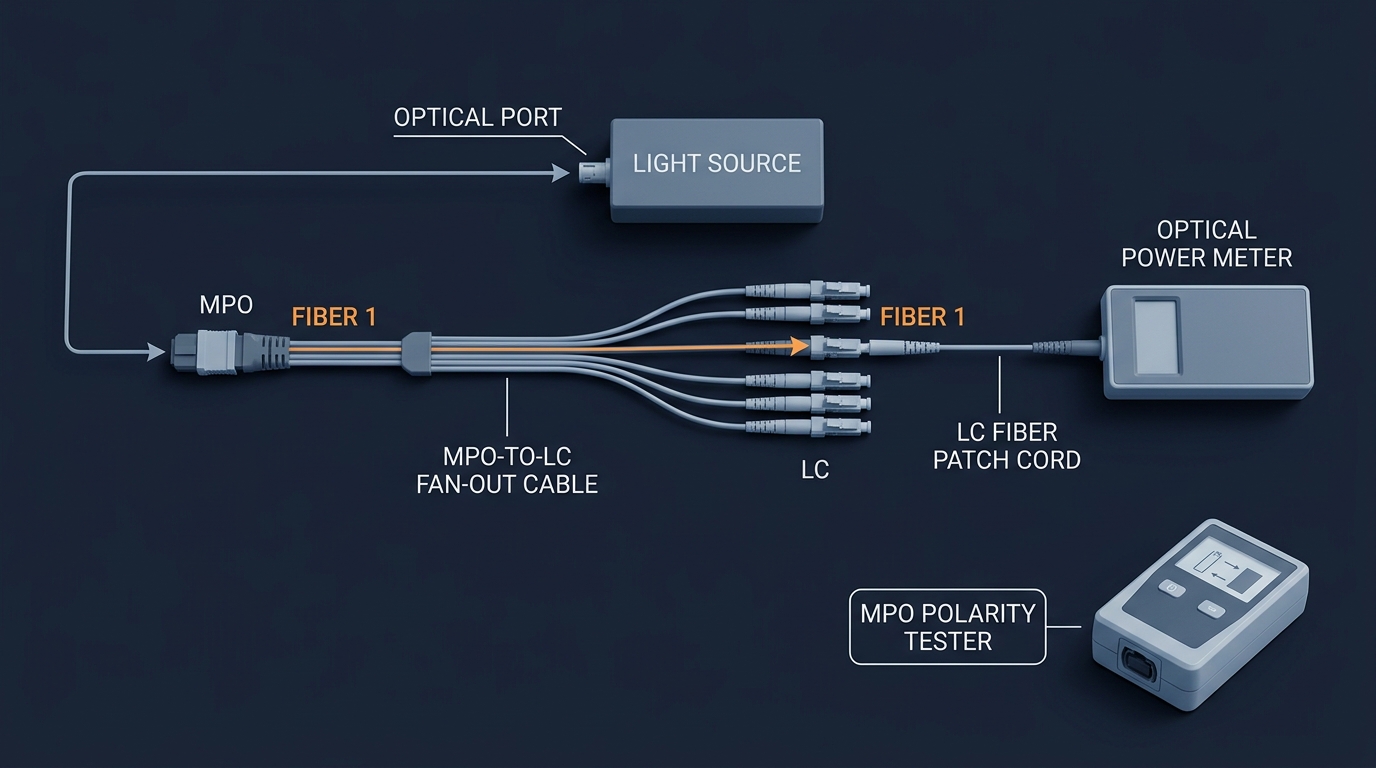
Figure 3: Two ways to verify MPO polarity — per-fiber testing with a fanout, or a one-shot multifiber polarity tester.
What a passing test proves. A polarity test proves the mapping matches the design — it does not prove the design is right. Test against the intended method (A, B, or C), not just "it passes." That is why the field practice that saves the most time is testing the channel (patch cord + cassette + trunk + cassette + patch cord) against the method you planned, before you connect transceivers. If the channel mapping matches the method, the link will come up; if it does not, you found the flip before it cost you a maintenance window.
Ordering MPO Cables: The Three Fields That Prevent Polarity Mistakes
Most flipped links trace back to the purchase order, not the install. When you order MPO components, three fields on every line item decide whether the plant works: polarity type, gender, and polish. Get in the habit of specifying all three on every SKU, even when it feels redundant.
- Polarity type (A, B, or C) — the fiber mapping of the assembly, per this article. Order trunk, cassettes, and patch cords as one polarity family. A common practice is to standardize the plant on one method (Type B for parallel optics, Type A for cassette-based duplex zones) and only deviate deliberately.
- Gender (male/female, guide pins) — MPO trunks are conventionally female (no pins); the pins live on the patch cords or cassettes. Two males or two females cannot mate. Pin ordering mistakes are the second most common MPO damage cause, and they bend ferrules, so get the gender matrix right in the PO.
- Polish (APC for single-mode, UPC for multimode) — as noted above, an APC/UPC mismatch is a silent loss disaster. Write it on the PO, on the label, and on the rack documentation.
The chain that has to stay consistent is: switch port → patch cord → cassette (MPO-to-LC) → trunk → cassette → patch cord → switch port. The cassette terminates the MPO trunk into the LC duplex ports the equipment actually uses, and the polarity handling lives inside the module — a DYS MPO/MTP cassette, for example, is a factory-terminated module where Type A, B, or C mapping is fixed at build time. Order the whole chain from one supplier against one method, and the probability of a flipped link drops to near zero.
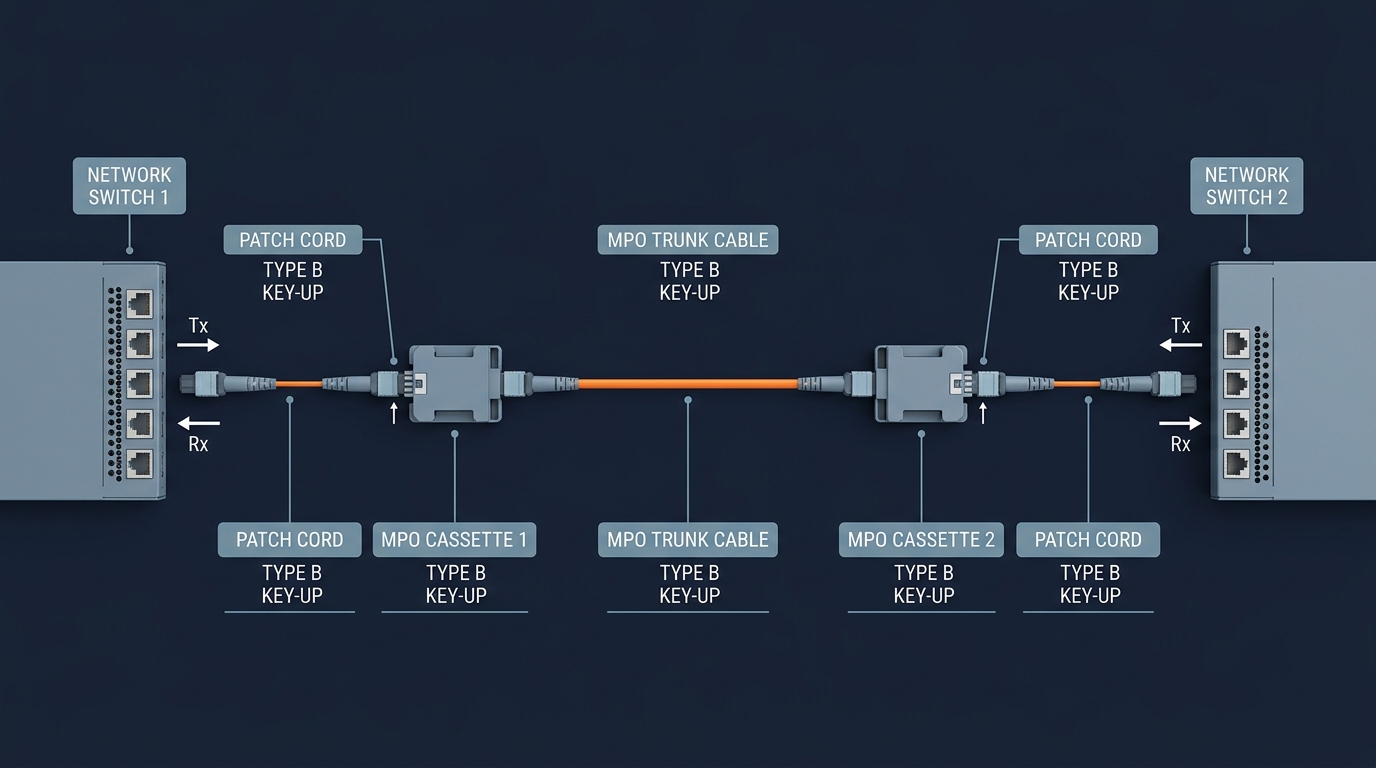
Figure 4: The full link chain — every segment carries a polarity type and key orientation, and they must all belong to one method.
Three ordering practices that pay for themselves:
- Write the method into the RFQ. "Type B, key-up to key-up, female trunk, UPC, 100% test data" is unambiguous; "MPO trunk, 16 fiber" is a coin flip.
- Ask for the test report. A per-assembly polarity + IL/RL report with serial traceability lets you prove the plant before you light it — standard practice for hyperscale buyers.
- Label everything. Polarity, polish, fiber count, and part number on the boot or label of every assembly. When the plant is 200 trunks deep, the label is the only documentation anyone will actually read.
If you are sourcing the full set — trunk, fanouts, cassettes, patch panels, and polarity-conversion adapters — the MPO/MTP data center cabling product line covers the range from 8 to 144 fibers, built to the polarity/gender/polish matrix you specify.
MPO Polarity for 400G and 800G: Type B by Default
The 400G and 800G generation changed the polarity conversation in one important way: parallel optics made Type B the default for new high-density plants. A 400G-SR4/DR4 link uses 8 fibers on an MPO-8 connector; an 800G-SR8/DR8 link uses 16 fibers on an MPO-16. Both are parallel links, and parallel links want exactly one reversal in the middle of the chain — which is what a Type B trunk provides. Mixing in Type A trunks at this speed means adding a crossed patch cord somewhere in every link — more SKUs and more failure points.
Two migration realities to plan around:
- Your existing plant may be Type A. A cabling plant built for 100G-era MPO-12 trunks is often Type A with cassette breakouts. That is not a defect — it is a signal that the 800G step will involve more than a transceiver swap. The migration paths, fiber counts, and loss-budget math are covered in our 400G to 800G data center cabling guide, which is the companion piece to this one.
- MPO-16 trunks are the new standard for 800G. If an 800G-SR8 or 1.6T upgrade is plausible in the trunk's life, size for MPO-16 now — and specify its polarity the same way you specified MPO-12: one method for the whole plant, Type B for parallel zones.
The Ethernet optics themselves are standardized in the IEEE 802.3 suite, which is where the lane counts and reach classes come from; the cabling-side decisions (fiber type, connector count, polarity) follow from the optics. For the power/thermal and structured-cabling framing of the 800G decision, Cisco's 800G client optics white paper and Corning's 10G–400G structured cabling guide are both worth a read.
MPO Polarity FAQ
What is the difference between MPO Type A and Type B?
Type A maps fibers straight through (position 1 to position 1) with opposite key orientations; Type B fully reverses the array (position 1 to position 12) with key-up on both ends. In practice: Type B builds the single reversal a parallel-optics link needs into the trunk, while Type A needs a crossed duplex patch cord at one end.
Can you explain fiber polarity in simple terms?
Polarity is the rule that makes sure the light leaving a transmitter arrives at a receiver, not at another transmitter. In multi-fiber MPO systems, every fiber position has a defined role, and polarity is the end-to-end mapping that keeps Tx and Rx aligned across trunk, cassettes, and patch cords.
What are MPO cables?
MPO (multi-fiber push-on) cables terminate multiple fibers — typically 8, 12, 16, or 24 — in a single connector, enabling the high-density parallel links used in 40G to 800G data center networks. They come in trunk, harness, fan-out, and breakout forms.
What is the difference between LC and MPO cables?
LC connectors carry one or two fibers (simplex/duplex); MPO connectors carry many. Parallel optics need MPO; WDM and equipment breakouts use duplex LC. In a typical plant the trunk is MPO and the equipment side terminates in LC through a cassette.
Can polarity methods be mixed in one channel?
No. TIA-568 methods are meant to be used consistently end to end. Mixing Type A trunks with Type B cassettes, or the wrong duplex patch cords, is the classic flipped-link cause.
Which MPO polarity type is most common?
Type B for parallel-optics links (the default for 40G/100G/400G SR4/DR4 and 800G SR8); Type A for cassette-based duplex structured cabling; Type C is legacy and rare in new designs.
Conclusion
MPO polarity explained in one sentence: decide your method once, order every component — trunk, cassette, patch cord — to match it, and verify the mapping before you light the link. The three types (A, B, C), the key-up/key-down mechanics, a testing step that catches flips, and a three-field ordering habit are the entire toolkit. Get those four things right and the flipped-link failure mode stops being a mystery you debug at 2 a.m. and becomes a checkbox you ticked at the ordering stage.
If you are planning a high-density MPO deployment and want the polarity, gender, and polish matrix specified correctly from the start — or need per-assembly test data for an existing plant — the DYS engineering team works from your drawing or spec, with 100% factory testing on every assembly. Send your RFQ with the link design and get a build-and-test quote back.