

Connectors
APC vs UPC Connectors: Return Loss, Green vs Blue
APC and UPC are the two singlemode connector polish standards you will actually spec in the field: APC (green, 8° angled endface, return loss ≥ 60 dB) for FTTH, PON, and RF-video links; UPC (blue, curved flat endface, return loss ≥ 50 dB) for data centers and enterprise LAN. The rule that decides everything: never mate an APC connector with a UPC connector—the endfaces are physically incompatible, and forcing them together damages both the connectors and, potentially, the transmitter.
This guide walks through return loss numbers, the green-vs-blue color code, and a step-by-step decision path so you can pick the right polish grade the first time—on the drawing board and in the truck.
APC vs UPC at a Glance: Green vs Blue in One Table
If you only have thirty seconds, this table is the answer. Every row is expanded further down the page.
Property | APC | UPC |
|---|---|---|
Full name | Angled Physical Contact | Ultra Physical Contact |
Endface | 8° angled | Flat with slight curvature (0°) |
Typical return loss | ≥ 60 dB | ≥ 50 dB |
Connector color | Green | Blue |
Typical fiber | Singlemode | Singlemode and multimode |
Main applications | FTTH/PON, RF video, WDM, outside plant | Data centers, enterprise LAN, short-reach digital links |
Can they mate together? | No | No |
The color is not cosmetic. It exists so that a technician can tell the polish grade apart at a glance, and standards bodies (TIA and IEC) built the green/blue convention into the connector and adapter design on purpose.
What the Acronyms Mean: Two Ways to Polish a Ferrule
Both APC and UPC describe how the end of the fiber—inside the ferrule, the ceramic tip that holds the fiber—is shaped and polished. That shape controls what happens to light at the connection point.
UPC (Ultra Physical Contact) is the refinement of the older PC (Physical Contact) polish. The endface is ground nearly flat, then domed with a slight curvature so the fiber cores make firm physical contact when two connectors are mated. For singlemode, typical return loss lands around 50 dB; for multimode, the numbers are looser because back reflection matters less over short multimode links.
APC (Angled Physical Contact) takes the same idea and adds an 8° angle to the endface. The fiber still contacts fiber, but the angle redirects reflected light into the cladding instead of straight back toward the laser. That single geometric change pushes return loss from roughly 50 dB up to 60 dB or better—a tenfold reduction in reflected power (every 10 dB is a factor of ten).
The ferrule itself is the same ceramic material in both cases; the difference is entirely in the polish geometry. For a broader look at the connector families that carry these polishes—LC, SC, FC, ST, MPO—see our guide to fiber optic connector types: LC, SC, FC, ST, and MPO.
Return Loss: The Real Difference That Matters
Return loss (also called back reflection or optical return loss, ORL) measures how much light bounces back toward the source at a connection point. It is expressed as a positive dB number—the higher, the better. A return loss of 60 dB means the reflected light is 60 dB below the incident light.
Two numbers matter in every fiber link, and they are easy to confuse:
- Insertion loss—light lost through the connection (signal attenuation). This is what you budget for in a loss budget.
- Return loss—light reflected back toward the transmitter. This is what can destabilize lasers and corrupt analog signals.
Fluke Networks' return loss explainer and Cabling Installation & Maintenance's definition give the same core definition: back reflection is a ratio of reflected to incident power, measured in dB, and it is worst at the air-glass interface of a connector or splice.
Why does APC's 8° angle matter so much? On a flat (UPC) endface, reflected light returns along the same path it came in on—straight back into the fiber core. On an angled APC endface, the reflected light exits the core into the cladding at an angle, where it attenuates quickly. The result: APC connectors routinely test at 60 dB or better return loss, while good UPC connectors sit around 50 dB.
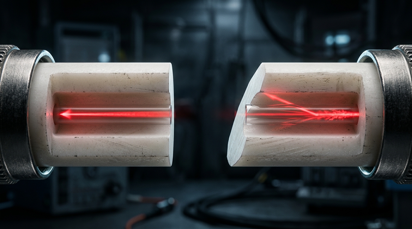
The 8° APC endface deflects reflected light into the cladding; the flat UPC endface reflects it straight back toward the source.
The applications that need that extra 10 dB are the ones where reflected light actively disrupts the signal:
- Analog / RF transmission—reflections create interference and ghosting that digital systems shrug off.
- High-wavelength WDM systems—reflected light at 1490–1625 nm can interfere with other channels.
- High-bit-rate singlemode links—laser transmitters (especially uncooled DFBs) are sensitive to back reflections, which can cause jitter, chirp, and bit errors.
If the link is digital, short, and singlemode—or multimode at any distance—UPC's 50 dB is more than enough headroom. That is the entire decision in one sentence: sensitivity to back reflection decides the polish grade.
A dirty endface makes all of this worse: contamination scatters light and degrades both insertion and return loss, which is why inspection and cleaning matter on APC and UPC connectors alike before every mating.
Green vs Blue: Color Coding, and What Happens When You Mix Them
The color code is the fastest identification tool you have. Per the fiber optic color coding rules used across the industry:
- APC = green—boots, housings, and adapters are green.
- UPC = blue—boots, housings, and adapters are blue.
The same convention carries into adapters and bulkheads: an APC port has a green adapter, a UPC port a blue one. When you see a green adapter on an OLT or ONT, the mating connector must be APC; a blue adapter means UPC. Belden's APC vs. UPC explainer makes the same point from the manufacturer side: UPC connectors are blue, APC connectors are green, and the difference is visible before you even touch the cable.
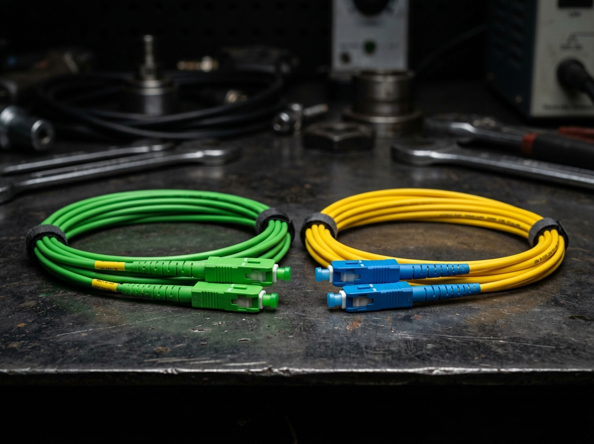
Boot and housing color is the fastest field check: green means APC, blue means UPC.
Never mate APC with UPC. This is not a performance nicety—it is physical damage waiting to happen:
- The 8° APC endface and the flat UPC endface cannot align core-to-core. Light scatters at the interface, and insertion loss spikes.
- Worse, the angled APC surface presses against the flat UPC surface at an angle, which can chip, crack, or score both ferrules.
- Reflected power can bounce back into the transmitter with enough energy to damage laser diodes in expensive equipment.
The failure is silent at first: the link may still pass for a while, then fail intermittently as the damaged endfaces degrade. Once a connector has been mated to the wrong polish, the ferrule is compromised and should be re-terminated or replaced.
Where APC Belongs: FTTH, PON, and RF Video
If your network carries PON signals, RF video, or any analog optical signal over singlemode fiber, you spec APC. This is the polish grade you will find across the FTTH ecosystem:
- OLT and ONT ports—GPON, XGS-PON, and NG-PON2 OLT ports ship with green SC/APC adapters. The ONT side matches with SC/APC pigtails and patch cords.
- PLC splitters—the splitter's input and output pigtails are SC/APC in almost every FTTH deployment, because the splitter is in the return-loss-critical path between OLT and subscribers.
- RF video overlay—cable operators pushing RF video over the same fiber as data need APC's back-reflection suppression, because analog signals visibly degrade with reflections.
- Outside plant and WDM—drop closures, terminal boxes, and WDM muxes in the outside plant use APC to keep long-haul and high-wavelength links stable.
In an FTTH build, the practical consequence is that everything in the optical path—OLT side, splitter, drop cable terminations, ONT side—uses SC/APC. One exception to remember: the cable itself does not care about polish grade. The polish lives in the connectors and pigtails, which is why an FTTH drop cable can be shipped unterminated or terminated with whatever connector the deployment plan calls for. For the drop-side hardware, our FTTH drop cable and termination guide covers the cable side of that decision. CommScope's FTTX guide is a good reference for the full PON architecture context.
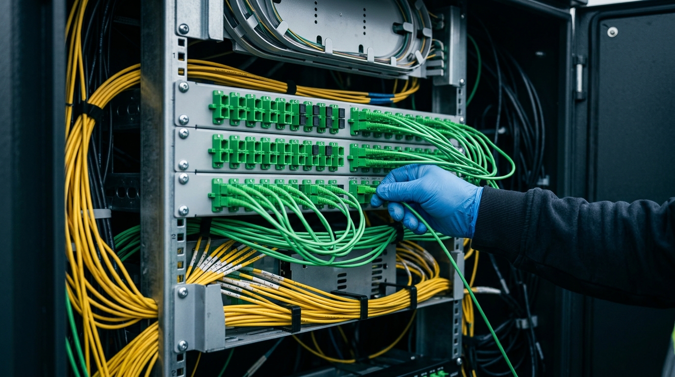
In a PON deployment, the OLT, splitter, and ONT sides all terminate with green SC/APC connectors.
Where UPC Belongs: Data Centers and Enterprise LAN
Flip to the other side of the industry—data centers, enterprise LAN, and short-reach singlemode links—and UPC is the default. The reasons are practical, not ideological:
- No analog or RF signals. Data center links are digital and short. The back-reflection sensitivity that drives FTTH to APC simply does not apply.
- Cost and availability. UPC polish is simpler to manufacture, which shows up in per-unit cost and in how widely available UPC patch cords, pigtails, and adapters are.
- Multimode compatibility. Multimode fiber—OM3, OM4, OM5—is exclusively UPC/PC territory. If your data center has any multimode links, UPC keeps the inventory uniform.
- The MPO ecosystem. MPO/MTP trunk assemblies, cassettes, and fan-outs are built around UPC polish for singlemode. If you standardize on APC in a data center, MPO-based structured cabling becomes a problem rather than a solution. Our MPO vs. MTP connector comparison digs into that ecosystem.
There is one data-center exception worth knowing: long-reach singlemode optics (like 10G LR, 100G LR4, or coherent DWDM transceivers) are more sensitive to back reflection than short-reach optics. In practice, most of these optics still specify UPC, and only very long, high-power, or analog-sensitive links migrate to APC. FS.com's PC vs. UPC vs. APC guide covers exactly this boundary between the three polish grades.
So the data center rule in one line: blue by default, green only when the optic or the link budget explicitly demands it.
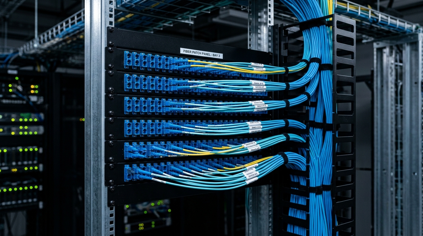
Data center structured cabling is blue/UPC territory, including the MPO/MTP ecosystem.
APC vs UPC: How to Choose (Step-by-Step Decision Path)
Stop reading application lists and run this four-step check instead. It takes two minutes and settles the question for any port, any project:
Step 1 — Read the port. Look at the adapter or bulkhead you are connecting to. Green adapter → APC. Blue adapter → UPC. If the adapter is unlabeled or missing, check the device datasheet or the transceiver's spec: optical transceivers state the required polish grade (for example, "SC/APC" or "LC/UPC") in the product specification.
Step 2 — Identify the network topology. PON (GPON/XGS-PON), RF video, or WDM over singlemode → APC. Point-to-point digital singlemode or multimode, data center, enterprise LAN → UPC. When a network mixes both—common in converged buildings—keep the two zones separate and label them.
Step 3 — Check the module, not just the port. An SFP/SFP+ transceiver has a specific polish requirement stamped in its spec sheet, and it must match the adapter and the patch cord. A green adapter with a UPC module is a mismatch even if the colors "look close enough." The FS return loss guide shows how module-level return-loss requirements flow into the same decision.
Step 4 — Write it into the BOM, explicitly. Every patch cord, pigtail, and adapter line in your bill of materials should state the polish grade: "SC/APC-SC/APC duplex, OS2" or "LC/UPC-LC/UPC duplex, OS2." Leaving polish grade out of the spec is how wrong-polish hardware ends up on a job site. When you order, confirm the grade in writing, and spot-check the boot color when the shipment arrives.
Procurement checklist:
This is the gap most comparison articles leave open: they list applications but never give you the check. Run the four steps and the answer falls out every time.
FAQ: What Installers Actually Ask
Is APC compatible with UPC? No. The 8° angled APC endface cannot mate correctly with the flat UPC endface. Forcing them damages the ferrules and can damage transmitters. Always match polish to polish.
How do I know if my SFP is UPC or APC? Check the transceiver's datasheet or product label—it states the connector type and polish (for example, "LC/UPC"). If the label is gone, look at the adapter it plugs into: green = APC, blue = UPC. When in doubt, treat an unknown port as needing verification, not as a guess.
What is the difference between LC, APC, and UPC? LC, SC, FC, ST, and MPO are connector types (ferrule size and coupling mechanism). APC and UPC are polish grades (endface geometry) that any of those types can carry—so you get combinations like SC/APC, LC/UPC, or MPO/UPC.
What does APC stand for in fiber connectors? Angled Physical Contact—the endface is polished at an 8° angle to redirect back reflections out of the fiber core. UPC stands for Ultra Physical Contact, a near-flat domed polish that achieves about 50 dB return loss.
Can I convert an APC connector to UPC? Not by re-polishing in the field—the ferrule geometry is machined and polished at the factory. Field re-polishing kits exist for APC-to-APC touch-ups, but converting between grades means re-terminating with a new connector.
Why is APC green and UPC blue? It is an industry color code adopted so technicians can identify polish grade at a glance: green for angled (APC), blue for flat/ultra (UPC). Adapters use the same colors.
Bottom Line
APC and UPC are not competitors—they are two correct answers to different questions. APC (green, ≥ 60 dB return loss) is the answer for FTTH, PON, RF video, and WDM singlemode links. UPC (blue, ≥ 50 dB) is the answer for data centers, enterprise LAN, and short-reach digital links. The one absolute rule: never mix them.
DYS Fiber Optic manufactures both polish grades across its product lines—FTTH waterproof patch cords in SC/APC, LC Uniboot and MPO/MTP assemblies in UPC, and ODVA outdoor connectors in SC, LC, and MPO interfaces—so the choice comes down to your network, not to what one supplier happens to stock. For the full picture on connector types, polish grades, and termination, start at our fiber optic connectors hub. If you need help specifying the right polish for a project, contact our engineering team for a free spec review.