
Connectors
Connector Ferrules: Zirconia vs Metal, Tolerances, and Why They Decide IL and RL
"Connector ferrule" names two different parts, depending on which side of the trade you stand on: the wire ferrule is a metal sleeve you crimp onto a stranded copper conductor, and the fiber-optic ferrule is the sub-micron precision bore that holds a 125 µm glass cladding on the connector's optical axis. This guide is about the second one — and about why its tolerances, more than its material label, are what you hear in a loss budget.
Two connectors can carry the same part number, the same green APC boot and the same cable, and still differ by 0.3 dB per mated pair — because one ferrule was produced to a 1.0 µm concentricity window and the other to 0.3 µm.
That sentence is the whole article in miniature. A ferrule is a mechanically simple object: a cylinder with a hole through it. What makes it the most consequential part of a fiber connector is that the hole has to be centered to a fraction of the core it is aligning, and the end of the cylinder has to be shaped to nanometer tolerance so that two fibers touch rather than almost touch. Everything downstream — insertion loss, return loss, whether a 400G link stays inside its 1-2 dB budget — is geometry you cannot see.
If you need the wider map first, the connector families and polish grades this ferrule sits inside are covered in the cluster guide; this page goes down one level, into the part itself.
Key takeaways
- A ferrule is an alignment component, not a connector body. It performs two jobs: it holds the bare fiber so its core sits on the connector axis, and it defines the mating plane where two fibers meet. Both jobs are dimensional, which is why a ferrule is specified in micrometers and nanometers.
- The two numbers that move insertion loss most are the bore (inner diameter) and concentricity. Commercial ferrule grades run from a ≤1.0 µm concentricity window down to ≤0.3 µm, and lateral core misalignment costs decibels, not tenths of a decibel.
- Material is a failure-mode decision, not a ranking. Zirconia takes the tightest bore and the best polish; machined metal survives vibration and impact but historically brought adhesive and expansion problems to glass fiber; polymer is not a downgrade in the one place it is the industry standard (MT/MPO).
- Endface geometry is the second half of the story. Radius of curvature, apex offset and fiber height are what turn a good bore into physical contact — and the inter-laboratory spread on curvature alone averaged 0.74 mm in the study metrology labs cite, which is why your incoming inspection and your supplier's certificate will not agree to the last digit.
- Grade labels are connector-level promises. An IEC 61753-1 Grade B jumper (≤0.25 dB maximum for >97% of randomly mated samples) can only be delivered by ferrules bought at a matching concentricity grade. Grade B is a ferrule purchasing decision before it is a marketing label.
What a ferrule actually does
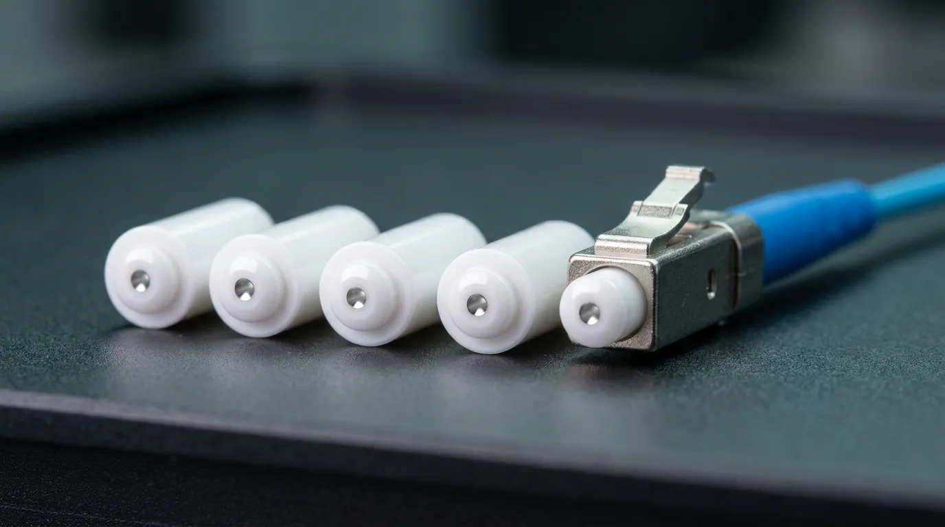
Strip a connector down and the ferrule is the small white cylinder at the tip — the part you see when you look into an adapter. It is not the housing, not the latch, not the boot, and not the spring. It is the only component whose dimensions sit directly in the light path.
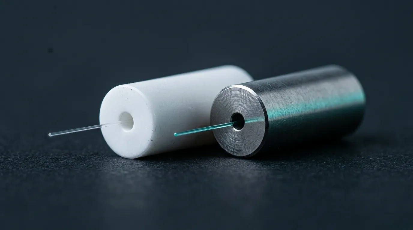
Job one: hold the fiber on axis. A single-mode fiber is a 9 µm core inside a 125 µm glass cladding. The ferrule's bore accepts that cladding — nothing else; the coating and aramid yarn stop at the crimp body. Whatever lateral offset the bore introduces between the fiber core and the ferrule's outside diameter is inherited by every mating that connector will ever make, and it does not improve with cleaning or re-termination.
Job two: define the mating plane. The ferrule's endface is polished, usually into a slight convex dome, so that two mated ferrules touch fiber-to-fiber under spring load rather than sitting apart with an air gap. The shape of that dome — and the amount by which the fiber protrudes from it — controls reflectance and part of the loss.
Those two jobs explain the two numbers that appear on every ferrule order line:
Dimension | What it controls | Typical scale |
|---|---|---|
Inner diameter (bore) | How closely the cladding is held, i.e. lateral offset | 125 µm class, held inside a ~1 µm window on the tightest grades |
Concentricity (bore-to-OD) | Position of the fiber core on the connector axis | ≤1.0 µm standard, ≤0.5 µm premium, ≤0.3 µm low-loss classes |
Outer diameter | Fit in the alignment sleeve, and the mating reference | 2.5 mm (SC, FC, ST) or 1.25 mm (LC, MU) |
Endface geometry | Whether physical contact actually occurs | Radius of curvature in millimeters; apex offset in micrometers; fiber height in nanometers |
The outer diameter splits the market cleanly in two: the 2.5 mm ferrule family (SC, FC, ST, E2000) and the 1.25 mm family (LC, MU, and the newer CS/SN dual-ferrule designs built on the same 1.25 mm tip). A 1.25 mm LC ferrule and a 2.5 mm SC ferrule are not variants of one part — they are different components with different sleeve hardware, different polishers and, usually, different production lines. The interface standards that fix which connector uses which ferrule are the IEC 61754 series; the optical interface of a single-mode physically contacting zirconia ferrule — its dimensional limits, in both the 2.5 mm and 1.25 mm sizes — is specified separately in IEC 61755-3-1.
Zirconia vs metal vs polymer: which material fixes which failure mode
Most ferrule comparisons are a properties table that ends with "ceramic is best". That is true and useless: it tells a buyer nothing about when the other two materials are the right answer. The useful framing is by failure mode — decide what your connector has to survive, and the material follows.
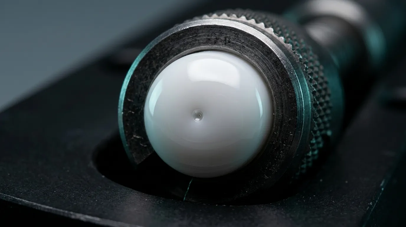
Zirconia ceramic (ZrO₂) is the default for a reason that is mostly about fit with glass and about manufacturability. A ceramic ferrule starts as a molded blank; the maker's control of that molding is what sets concentricity, which is why molding technology is a supplier differentiator rather than a commodity step — Kyocera, for example, builds its ferrule line around extrusion molding of the blank, with the bore concentricity and the endface finished by precision machining. Ceramic also polishes to the mirror finish that physical contact requires, and its hardness holds that finish across mating cycles. The ceramic ferrule came out of Japan and is what ended the metal-ferrule era of the previous generation.
Machined metal (stainless steel, and specialty alloys) is the answer when the failure mode is mechanical rather than optical. The SMA connector — the first widely used multimode connector, built by Amphenol from "SubMiniature A" microwave hardware — used a precise 1/8 inch machined metal ferrule, and metal ferrules have stayed in vibration-heavy, high-mating-cycle and ruggedized applications ever since. The trade-off is documented rather than theoretical: the same reference notes that metal ferrules had a problem with glass fiber, because uneven expansion coefficients between metal, adhesive and glass sometimes let the fiber move or the joint fail. A machined surface is also a poor starting point for the sub-micron bore roundness and mirror polish that tight insertion and return loss budgets assume.
Polymer is the compromise material — except where it is not a compromise at all. Glass-filled plastic ferrules appeared before ceramic did — the FOA's connector history records that the Biconic was molded from a glass-filled plastic that was "almost as hard as ceramic" — and they remain the standard answer for multi-fiber array connectors, which the next section covers as a deliberate exception.
Failure mode you are designing against | Material that fixes it | Why |
|---|---|---|
Micrometer-scale lateral offset; tight IL/RL budget | Zirconia ceramic, tightest concentricity grade | Molded-then-machined to sub-micron bore and concentricity control |
Repeated mating cycles, abrasion, cleaning | Zirconia ceramic | Hardness plus polishability: the endface survives handling |
Vibration, shock, mechanical abuse, harsh environment | Machined metal (or a ruggedized ceramic design) | Mechanical strength and toughness where the connector, not the polish, takes the load |
High-density multi-fiber arrays (MPO/MTP) | Glass-filled PPS polymer (MT ferrule) | Precision molded in one shot; pins, not a sleeve, do the alignment |
Low-cost, short, uncritical in-equipment links | Polymer | Adequate for non-critical optical paths; not for single-mode budgets |
The tolerance stack: bore, concentricity and outer diameter
Here is where the material debate stops mattering and the arithmetic starts.
The bore has to match the fiber, not a nominal number. Single-mode glass is drawn to a cladding diameter that is only nominally 125 µm. What a ferrule buyer has to match is the fiber maker's actual specification rather than the nominal number: a mainstream low-loss single-mode fiber is supplied to 125 ± 0.7 µm with core-clad concentricity ≤ 0.5 µm. A ferrule bore therefore has to be both tight enough to align the fiber and loose enough to accept a real distribution of fiber diameters. SENKO's engineering note on the subject puts the workable pairing plainly: if single-mode fiber glass outer diameter typically runs 124.5-124.9 µm, the desirable ferrule inner diameter is 125-125.5 µm.
The outer diameter has an astonishingly small window. In the published interface tables of IEC 61755-3-1 — the standard that defines the 2.5 mm and 1.25 mm cylindrical full-zirconia PC ferrule interface — the 2.5 mm ferrule's outside diameter is limited to a 2.4985-2.4995 mm range, a total window of one micrometer, alongside a spherical radius of 5-30 mm and an apex offset of 0-50 µm. The ferrule is bolted to that window because the alignment sleeve, not the connector body, is what actually centers two mated ferrules.
Concentricity is the graded number, and it is the one you should be buying. Ferrule makers specify concentricity (bore-to-OD alignment) as a maximum, in grades: one supplier's published scheme runs ≤1.0 µm for standard-loss ferrules, around ≤0.5-0.6 µm for premium, and ≤0.3 µm for low-loss ferrules. Those are not marketing bands; the same note shows why. When it modeled a production population — ferrule inner diameter distributed around 125.35 µm against fiber outer diameter distributed around 125.0 µm — 5.3 % of ferrules could not fit over the stripped fiber at all. Tighten the bore for lower loss and you buy scrap and line slowdowns; loosen it and you give away decibels at every mating. That is the actual trade a ferrule grade expresses, and it is why the same supplier sells three grades rather than one best part.
Why micrometers turn into decibels. Insertion loss in a mated pair is dominated by lateral core misalignment — not by a longitudinal air gap, and not by angular tilt. SENKO's note plots the relationship directly: on a single-mode fiber the curve climbs steeply from a fraction of a decibel near zero offset to several decibels within the first few micrometers, which is why a 0.3 µm ferrule grade is worth paying for and why "the connector looked fine" is not an argument. Concentricity, bore fit and core eccentricity all feed that one axis of error, and they add rather than average: random mating means the offsets point in random directions, so the worst pairs in a population set the number your insertion loss and return loss budget has to live with.
Endface geometry: three measurements that decide IL and RL
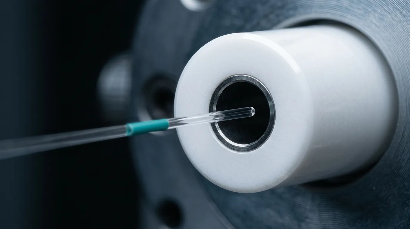
A ferrule with a perfect bore can still fail, because the endface is what makes physical contact. There are exactly three parameters to control, and the FOA's single-mode termination reference names them the way a production engineer would: radius of curvature, eccentricity of polish (apex offset), and fiber undercut or protrusion (fiber height). They are measured by interferometry — the procedure is standardized in IEC 61300-3-47 for PC and APC spherically polished ferrules.
Parameter | What it is | Interface window (IEC 61755-3-1 tables) | Practical acceptance |
|---|---|---|---|
Radius of curvature (ROC) | Radius of the polished dome | 5-30 mm | ~7-25 mm is the working range on PC tips |
Apex offset | Distance between the fiber center and the high point of the dome | 0-50 µm | ≤50 µm is the usual maximum |
Fiber height (protrusion/undercut) | How far the fiber sits proud of, or below, the fitted sphere | limit around −100 nm undercut, with allowed undercut varying by contact force | roughly −125 nm to +50 nm on interferometer practice |
Two things about that table are worth internalizing. The "practical acceptance" column is the band connector makers and metrology labs actually work to — a 7-25 mm radius window and a fiber-height band of roughly −125 nm to +50 nm, with a 50 µm apex-offset maximum in common use — which is the kind of production window endface metrology specialists publish, rather than a restatement of the standard's own limit columns.
The windows are wide on purpose, and one of them is a trade. A permitted undercut window exists because the interface standard has to accommodate different spring forces: the tables in IEC 61755-3-1 are accompanied by curves of allowable undercut as a function of endface radius and apex offset, for minimum contact forces of 4.9 N and 2.9 N. Too much protrusion and the fiber is fragile; too much undercut and the fibers never actually touch.
Your measurement will not reproduce your supplier's to the last digit, and that is normal. A NIST-coordinated interlaboratory comparison of endface geometry measurements on PC connectors — the study behind the numbers metrology labs quote — found that the PC endfaces it measured span radii between 10 and 25 mm, with an average measurement spread per specimen of 0.74 mm across participants (0.44 mm once one contact-interferometer method was excluded). The study also shows that protrusion/undercut changes materially depending on whether you define it against a fitted sphere or against a plane fitted to the bore edge. In other words: when your incoming inspection and your supplier's certificate disagree by a few tenths of a millimeter of curvature, neither instrument is necessarily broken.
Polish grade rides on top of geometry. A flat UPC endface and an 8° APC endface have different geometry limits — APC is standardized separately in IEC 61755-3-2 — and a different return-loss floor. The practical consequence for specification is the one most buyers already know: UPC (blue) tips are specified for return loss ≥50 dB and APC (green) tips for ≥60 dB, which is the value you will find on a Grade B single-mode patch-cord datasheet. The 8° APC endface and the return-loss step it buys is why FTTH plant standardizes on APC while data-center equipment usually does not.
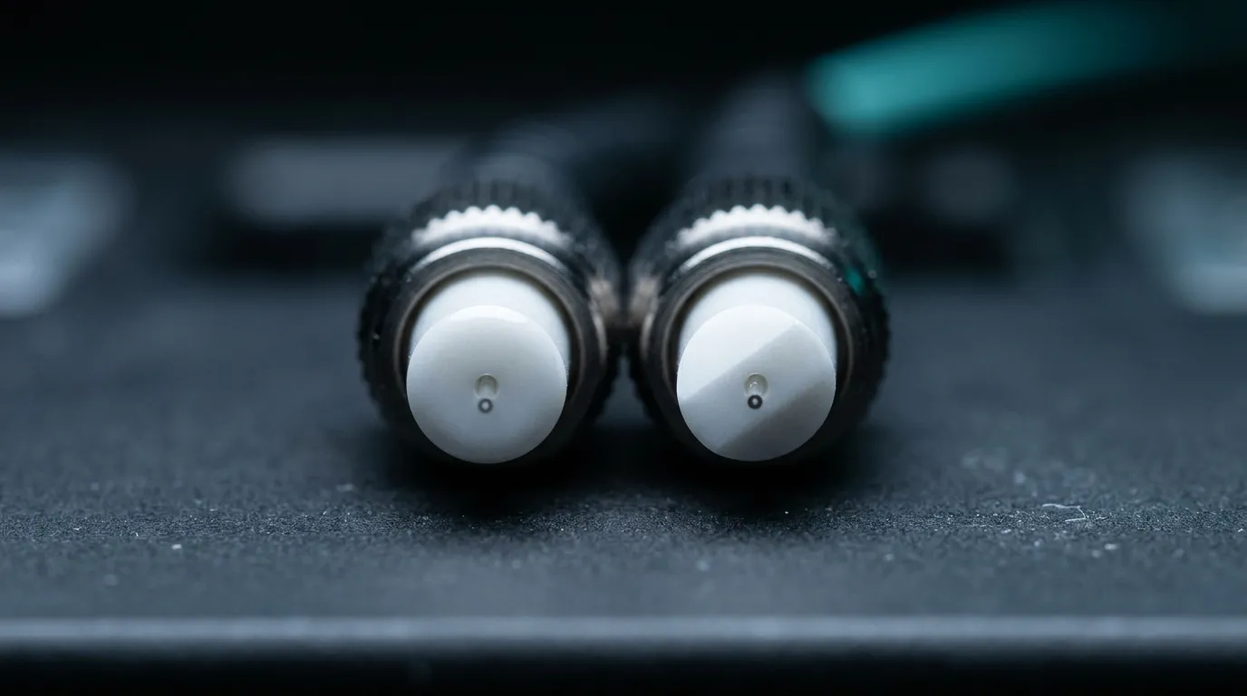
What "Grade B" buys you — and what it does not
Grade letters on a jumper datasheet are not decoration; they are IEC 61753-1 attenuation classes for randomly mated connectors in a controlled environment. The scheme most vendors publish, and the one restated in SENKO's ferrule application note, is (SENKO is itself a connector manufacturer, so treat the grade wording as a supplier's reading of the standard rather than the standard's own text):
Grade | Mean IL (random mated) | Max IL for >97% of samples | Budget for 10 connections |
|---|---|---|---|
A (proposed, not ratified) | ≤0.07 dB | ≤0.15 dB | ~0.7 dB |
B | ≤0.12 dB | ≤0.25 dB | ~1.2 dB |
C | ≤0.25 dB | ≤0.50 dB | ~2.5 dB |
D | ≤0.50 dB | ≤1.00 dB | unclear / wide |
Return loss is graded on a separate 1-4 scale, from ≥60 dB (mated, ≥55 dB unmated) at the top down to ≥26 dB; a UPC assembly is normally specified to ≥50 dB and an APC assembly to ≥60 dB.
The point buyers miss is that the grade is delivered by the ferrule. A Grade B guarantee is a promise about random mating — every plug against every other plug, not a hand-picked pair — which means it is a statement about the distribution of core offsets the manufacturer's ferrules produce. That is why premium ferrule grades (concentricity around ≤0.5 µm) are described as the parts with which Grade B is achievable without production-line slowdowns, while the tightest low-loss grade (≈≤0.3 µm) is what makes Grade A-class performance possible at the cost of occasional fiber-to-ferrule misfits. If you are buying grade on a datasheet and standard ferrules in the bill of materials, you have bought a label and not the performance.
Core eccentricity and "tuning": the lever most pages skip
Concentricity describes the bore's position relative to the ferrule's outside diameter. Core eccentricity describes where the fiber core sits inside that bore — a second, independent offset contributed by the fiber's own core-clad concentricity and by how the fiber settled during termination. Two connectors built from identical ferrules can have their cores offset in opposite directions, and random mating then adds the two offsets instead of canceling them. Ferrule makers do not publish core eccentricity as a catalogue number the way they publish concentricity, so it reaches a buyer either as a supplier commitment on the drawing or as a measurement on your own samples.
The industry's answer is tuning: measure each connector's core eccentricity and rotate the ferrule so the offset points toward the connector key. Mated key-to-key, two tuned connectors put both cores on the same side of the axis, and the residual offsets largely cancel. The interface standard accommodates the practice explicitly — IEC 61755-3-1 defines two variants of the interface, distinguished by whether the fiber core axis is oriented toward the connector guide key.
Tuning has a hard field caveat, and it is the reason tuning is not simply "the good option": it only pays off when a tuned connector mates with another tuned connector. Mate a tuned jumper with an untuned one and the advantage disappears, which is what happens every time an operator reaches for whatever patch cord is on the shelf. That is why the practical decision is usually: buy a concentricity grade good enough that random mating passes, and treat tuning as a bonus for reference cables and measured link-budget-critical runs rather than as a substitute for ferrule quality.
When the metal ferrule is the right answer
Metal ferrules are not a legacy mistake. They are the correct answer to a different question — "what survives this environment?" rather than "what minimizes loss at 25 °C with clean hands?"
Three situations genuinely favor them:
- Vibration and shock. Tower-top, industrial-robot, rail and military connectors see loads that a ceramic tip can crack. Metal deforms rather than shatters, and ruggedized connector designs lean on that toughness.
- Very high mating-cycle counts and abuse. Where the installation practice is unkind — repeated field mating, cable strain, dirty hands — the mechanical margin matters more than the last 0.1 dB.
- Sensor and instrumentation links. Short, often multimode, often not budget-limited; the fiber alignment demand is lower and the mechanical demand is higher.
What metal does not fix is the thing this article is about. A machined bore is harder to hold to sub-micron roundness and concentricity than a molded-and-lapped ceramic, and a metal endface is harder to bring to the mirror finish that physical contact needs. The historical adhesive problem is a warning about the whole assembly, not just the ferrule: metal, glass and epoxy expand at different rates, and in a temperature-cycling environment that difference shows up as fiber movement, voids and eventual pushback. If you choose metal, choose the termination process with it, and test it hot and cold.
The multi-fiber exception: MT ferrules are polymer on purpose
Everything above says "zirconia, tighter, better". Then you open a 12-fiber MPO and find a rectangular, glass-filled polymer ferrule with metal guide pins — and it is not a cost compromise.
This is the MT (mechanical transfer) ferrule, the alignment platform behind every MPO/MTP connector. Its alignment method is completely different from a single-fiber connector: there is no spring-loaded ferrule in a split sleeve. Instead, two rectangular ferrules butt together, and two stainless steel guide pins (typically 0.7 mm) in the male connector engage matching holes in the female, positioning an entire row of fibers at once. US Conec's own MT ferrule specification describes the material as highly glass-filled PPS, chosen for dimensional stability and low moisture uptake, with a fiber pitch of 0.25 mm and up to 12 fibers per row — and ferrule variants running to 72 fibers. The precision lives in the mold, not in a series of machining steps, which is the only economical way to place 12 or 72 holes to micrometer true position.
So the material rule survives, with a boundary drawn on it: use zirconia where the alignment is done by a bore and a sleeve around a single fiber; use glass-filled polymer where the alignment is done by pins across an array. The failure mode moves with it, too. An MT ferrule's weak point is not concentricity — it is cleanliness and endface damage across a large, hard-to-inspect area, where a single contaminated fiber hole can take out one channel of a 24-fiber trunk. The factory breakout assembly below shows the other end of that trade: one multi-fiber trunk fanning out into single-fiber legs, each with its own 1.25 mm-class ferrule to keep clean. The MPO/MTP systems and polarity rules that sit on top of this ferrule are covered in the data-center cluster.
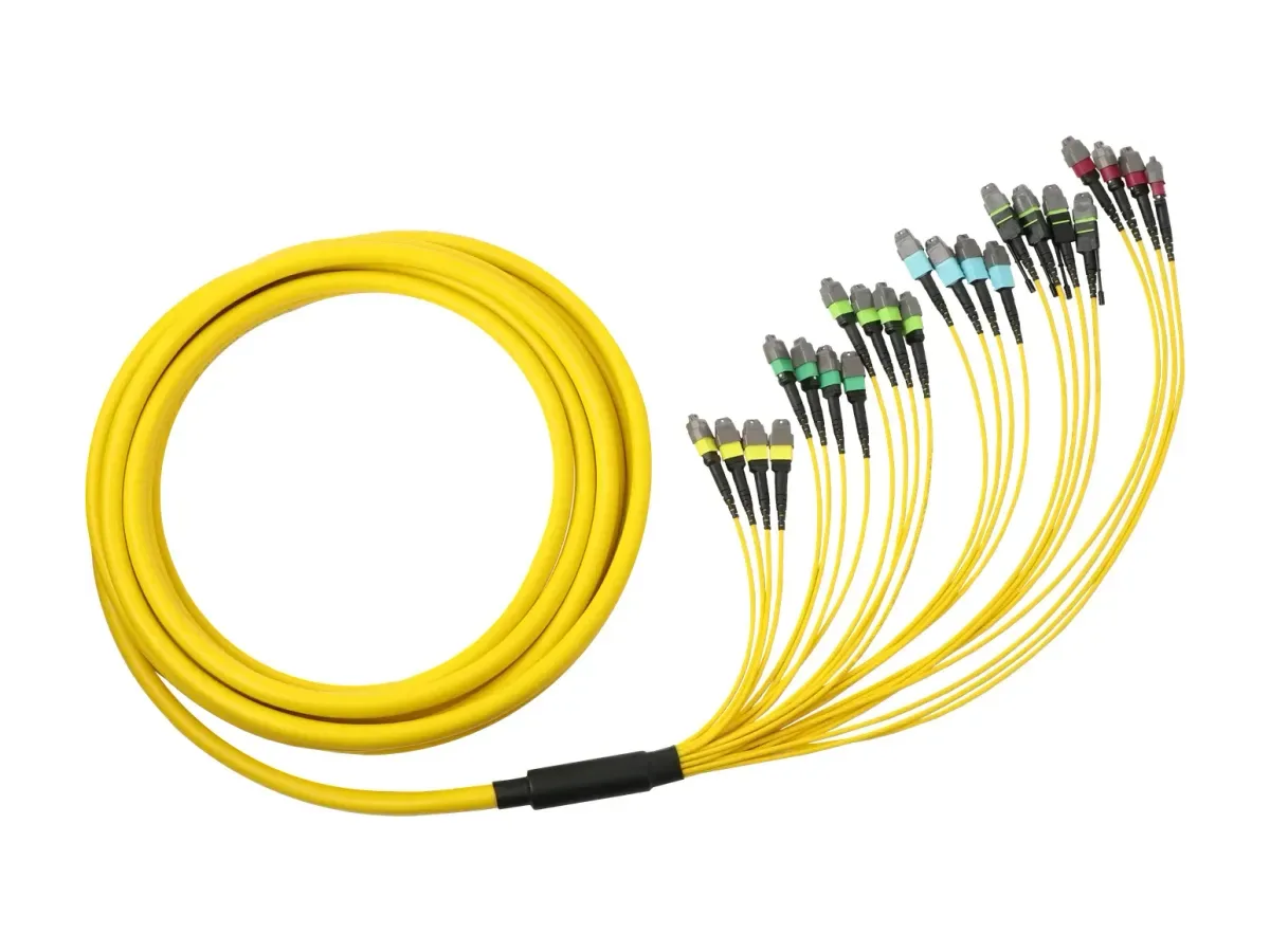
Specifying ferrules on a drawing and on goods-in
This is the section that turns the article into something you can act on. A ferrule purchase order needs six things stated, and most of them are routinely left implicit:
- Ferrule size and interface family — 1.25 mm or 2.5 mm, plus the connector interface it is for (LC, SC, FC, MU), because sleeves and polishers differ.
- Material — zirconia ceramic unless the environment justifies metal, and the MT polymer ferrule where the connector is multi-fiber.
- Bore (ID) as a range, not a nominal. Specify the window and both ends of it: too large costs loss, too small costs yield. Ask the supplier where their ID distribution sits, not just its limit.
- Concentricity grade as a maximum in µm — and make the grade meet the connector grade you are selling. A Grade B jumper claim behind ≤1.0 µm ferrules is not a Grade B part in random mating.
- Endface geometry limits — ROC range, apex offset maximum, fiber height window, and which standard's table you are invoking (IEC 61755-3-1 for PC zirconia; 61755-3-2 for APC).
- Measurement method and sample plan — interferometer type for geometry, how concentricity is verified, and the sampling rule (for example, AQL-based sampling per lot rather than a single certificate of conformity).
On goods-in, the two checks that actually catch problems are a dimensional check of bore and concentricity on a sample, and an interferometric geometry scan of the endface — not a visual look under a microscope, which catches contamination and chips but says nothing about whether physical contact will occur. Keep the measurement uncertainty in mind when you set the pass/fail limits: the NIST interlaboratory study's spread on curvature was the same order as the difference between acceptable and marginal parts, so a limit set at the exact standard boundary will generate disputes. Set limits with margin, and agree the method with the supplier before the first lot. If the environment is the reason you are buying, that decision lands on real hardware — an IP68 hardened outdoor assembly is a ferrule choice plus a housing choice, and only the ferrule half shows up in a loss budget. Field verification of what you bought — endface inspection and loss testing — is the other half of that loop.
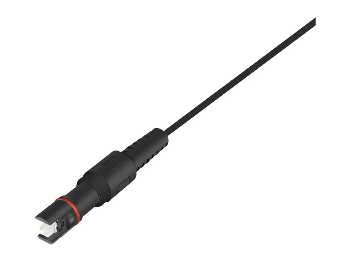
Five ferrule failure modes seen in the field
Symptom | Likely ferrule cause | What to check |
|---|---|---|
IL drifts upward after repeated mating | Fiber pushback — the fiber has withdrawn from the endface | Epoxy/adhesive selection and cure, ferrule-fiber expansion mismatch, spring force |
One connector in a batch consistently 0.2-0.4 dB worse | Core eccentricity / concentricity outlier, or a tuning error | Concentricity grade of that lot; whether the connector was tuned and mated to an untuned jumper |
High reflectance, low IL looks acceptable | Undercut or apex offset outside window — no physical contact | Interferometric geometry scan: ROC, apex offset, fiber height |
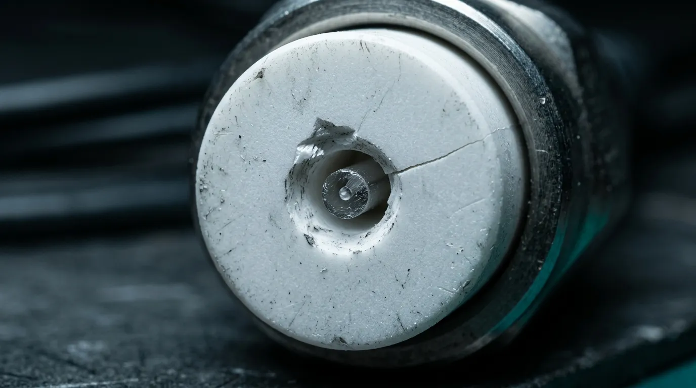
Intermittent loss that changes when the cable is moved | Cracked or chipped ferrule, often from mis-mating or a dropped adapter | Magnified endface inspection; look for chips at the bore edge |
Loss after cleaning keeps returning | Epoxy void or polish pit at the fiber edge; contamination trapped at the bore | Endface inspection after cleaning; polish process audit |
The common thread is that none of these are visible as a "bad material". They are all tolerance, process or handling outcomes — which is exactly why a ferrule specification is worth more than a ferrule brand claim.
The ferrule in one paragraph
A connector ferrule is the component that holds the fiber on axis and defines the plane where two fibers meet, and everything a buyer cares about follows from two numbers and three measurements. The numbers are bore diameter (matched to a 125 µm cladding that itself varies) and concentricity (graded from ≤1.0 µm down to ≤0.3 µm, and the real source of random-mating loss). The measurements are radius of curvature, apex offset and fiber height, which decide whether physical contact happens at all. Material answers the environment question — zirconia for alignment precision, machined metal for mechanical abuse, glass-filled polymer where alignment is done by pins across an array — but it never substitutes for the tolerance you bought. Write the tolerance on the drawing, sample it on goods-in, and test what you installed.
Manufacturing a ferrule to a tolerance is one problem; proving you held it is another. DYS Fiber Optic builds the passive and connector side of that chain — SC, LC and APC assemblies, field-installable fast connectors, factory-terminated pigtail assemblies and MPO/MTP trunk cables — and runs an in-house reliability lab for exactly the measurements this article has been describing: a 3D interferometer for endface geometry, insertion/extraction force stations for the mating-force side of pushback, and a precision mold workshop that gives it control over connector tolerances and ferrule alignment, with test methods written to GR-326 and 100% pre-shipment testing. For operators and integrators in Europe, the US and emerging markets, that makes a ferrule specification something to argue with numbers rather than adjectives. If your next project has a ferrule tolerance on the drawing, review the FTTH cabling and connector range or ask for samples to test against your own plant before a design is frozen.