
Connectors
Fiber Pigtails: Types, Splice Workflow, and Fast Connectors
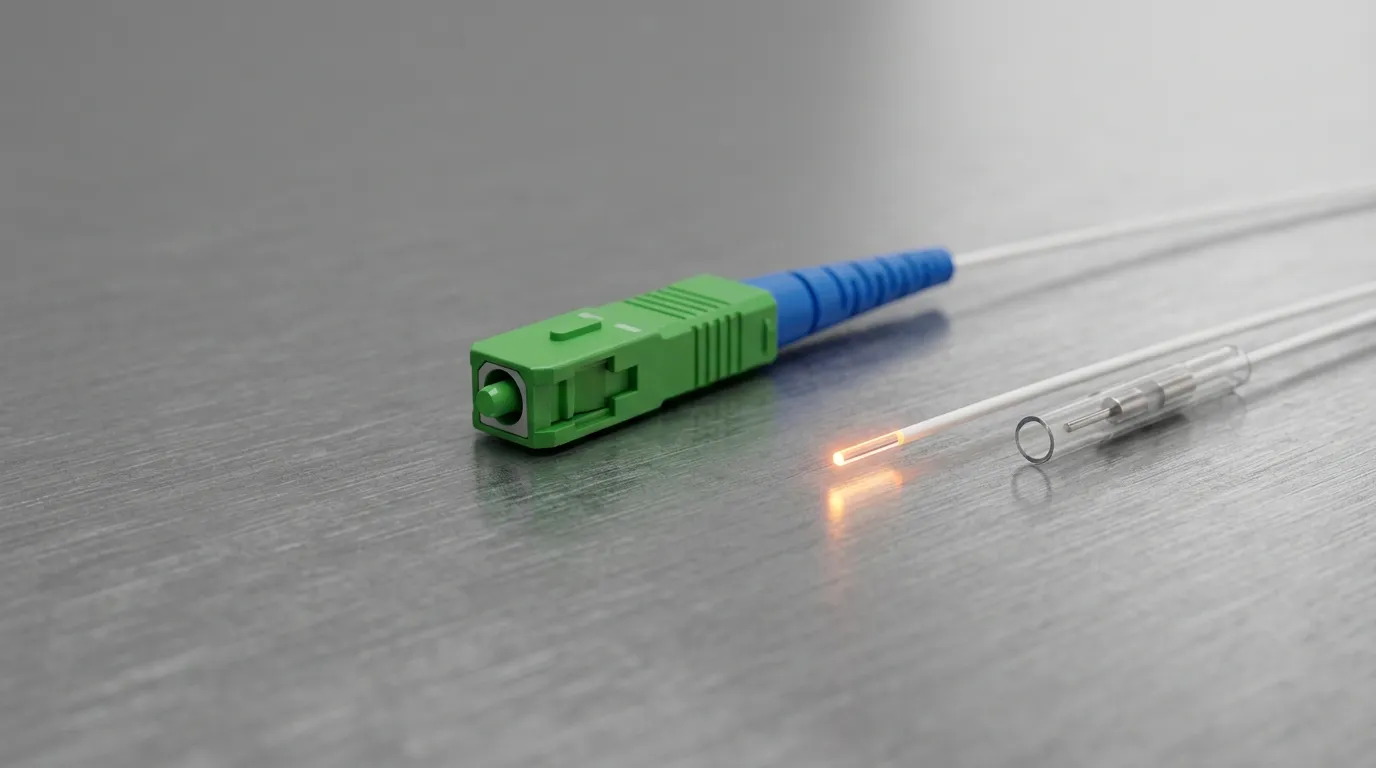
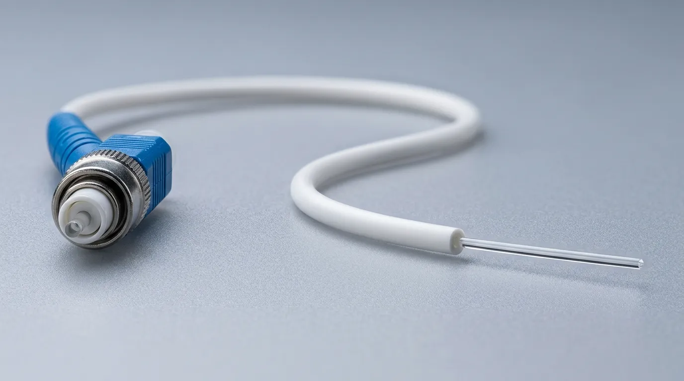
A fiber pigtail is a short length of optical fiber with a factory-terminated connector on one end and bare fiber on the other. The connector end is polished, inspected and tested under factory conditions; the bare end is fusion spliced or mechanically spliced to the installed cable in the field. That split personality is the whole point of the component — and it is also where most specification mistakes start.
Here is the number worth remembering before anything else: the termination loss of a pigtail is not the connector's loss. It is the mated connection loss plus the splice that attaches the pigtail to your cable. Both segments sit inside your link budget. Standards and datasheets list connection losses that already account for this, which is why a pigtail assembly can carry a max loss figure that looks worse than the connector on its own — and why comparing a pigtail against a field-installable connector on "insertion loss" alone gets you the wrong answer.
This guide covers what fiber pigtails are and how they differ from patch cords, the type dimensions that actually change a specification, the loss numbers and standards worth putting on a datasheet, an eight-step field splice workflow with pass/fail criteria, and an honest comparison between splicing a pigtail and terminating with a field-installable connector.
What a Fiber Pigtail Is, and the Number Most Buyers Forget
A pigtail has one connectorized end and one raw end. The connectorized end mates with equipment or a patch panel; the raw end is where your cable's fiber gets joined to it. In single-mode outside-plant work this is the default approach: most field single-mode terminations are made by splicing a factory-made pigtail onto the installed cable rather than terminating the fiber directly, because single-mode polishing is difficult to control in the field, especially for reflectance.
Two structural details follow from that:
- The fiber is usually 0.9 mm tight-buffered. It has enough protection to survive inside a splice tray or closure, and not much more. Pigtails are designed to be protected by an enclosure, not to be pulled through a building.
- Both ends matter for loss. A factory end face is measured against a reference connector; the splice you make in the field adds its own loss and its own reflectance. Total termination loss = connection loss + splice loss. That composition is not an approximation — a splice-on termination's stated connection loss is defined to include the splice that attaches it, which is why assembly datasheets can quote maximum losses that look worse than the bare connector.
This is the difference between a pigtail and a fiber optic patch cord: a patch cord is terminated on both ends and is meant for reconfigurable, outside-the-enclosure routing; a pigtail is terminated on one end and is meant to be permanently spliced. Sizing, jacket, and price all follow from that. If you are still deciding which connector interfaces belong in the design at all, the complete guide to fiber optic connector types covers the family this component belongs to.
The Types of Fiber Pigtails That Actually Change the Specification
Most pigtail pages classify by connector name and stop. Procurement and design care about six dimensions, because each one changes a line on the spec sheet or a step in the work method.
Fiber type. OS2 single-mode is the default for anything leaving a building or crossing a PON. Multimode (OM3, OM4, OM5) still shows up in short-reach data center and enterprise runs, where 12-fiber and 24-fiber bundles are common. Single-mode pigtails use a 9 µm core; multimode uses 50 µm (OM2–OM5) or 62.5 µm (OM1). If you are specifying by grade rather than by name, the differences between single-mode and multimode fiber are the right starting point.
Connector interface. LC and SC cover the overwhelming majority of modern projects. FC (screw coupling) persists in test and lab racks, and ST survives in older multimode installations. The interface is dictated by the adapter panel you already own, not by preference. Multifiber interfaces such as MPO/MTP sit alongside these but are specified as arrays, with their own polarity and gender rules — they terminate a whole fiber array at once rather than one strand, so they change the tray and polarity plan rather than the splice method.
End face polish. UPC for flat physical contact, APC for 8° angled contact. This is not cosmetic: it directly sets your return loss, and mixing UPC into an APC port (or the reverse) produces a damaged or unusable interface. Where reflectance matters, APC is the requirement.
Construction. 0.9 mm tight-buffered for enclosures; 2.0 mm or 3.0 mm jacketed for exposed routing; ribbon construction where you are splicing 12 fibers at once; armored where the run is exposed to crushing or rodent damage.
Fiber count. Single-fiber dominates equipment-side work. 6-fiber and 12-fiber bundles — color-coded and ready to splice as a set — are standard for ODF and closure work, with 24 to 72 fiber bundles used in backbone splicing.
Environment. Indoor standard pigtails are the default. Waterproof pigtails using ruggedized connectors and PE jackets belong on towers, in outdoor closures and in any hand-hole where standing water is a realistic condition.
Dimension | Typical options | What it decides |
|---|---|---|
Fiber type | OS2 · OM3 · OM4 · OM5 | Link budget, distance, jacket color |
Connector interface | LC · SC · FC · ST | Mate with existing adapters and panels |
End face | UPC · APC (8°) | Return loss; UPC/APC must never be mixed in one path |
Construction | 0.9 mm tight buffer · 2.0/3.0 mm jacket · ribbon · armored | Survives inside a tray vs exposed routing |
Fiber count | 1 · 6 · 12 · 24–72 | Splicing time per enclosure; tray capacity |
Environment | Indoor · IP68 waterproof | Whether the assembly is legal for the location |
The practical takeaway from the matrix: the connector interface is usually a constraint you inherit, while construction and fiber count are the two dimensions where a buyer actually has room to reduce cost and install time. A 12-fiber color-coded bundle that matches the tray capacity will usually beat twelve single pigtails on labor time — provided the tray can hold the coils.
Loss Numbers and Standards: What Belongs on the Datasheet
Four numbers and a reference determine whether a pigtail is acceptable; a supplier who cannot produce them has told you nothing.
Connection loss. TIA-568 (ANSI/TIA-568.3) sets connection losses at less than 0.75 dB. That figure is deliberately generous — it has to accommodate prepolished/splice connectors as well as factory assemblies. Treat 0.75 dB as the ceiling, not the target. The Fiber Optic Association's termination reference is explicit about what makes the number move: field termination of prepolished/splice connectors with a precision cleaver holds around 0.5 dB consistently, while a simple cleaver drifts toward the 0.75 dB range.
Splice loss. Fusion splicing is the lowest-loss, lowest-reflectance and most reliable joint available — which is why essentially all single-mode splices are fusion, and why mechanical splicing tends to be reserved for temporary restoration and most multimode work. A welder that estimates its own splice loss and prompts the operator to remake a bad one is doing your quality control for you. A good splice contributes a small fraction of a dB; the splice protection sleeve you apply afterwards protects it mechanically, not optically.
Return loss (reflectance). This is where the polish grade shows up, and the numbers are well established:
- Air gap in the joint: roughly 5% Fresnel reflection, about 0.25 dB of loss per gap. No air-gap connector gets below about 0.3 dB, with reflectance around −20 dB.
- Flat physical contact (PC): typical loss about 0.3 dB, reflectance −30 to −40 dB.
- Convex polished ferrule: loss under 0.3 dB, reflectance −40 dB or better.
- Angled physical contact (APC): reflectance lower still, and the standard choice for FTTH, CATV, WDM and 5G fronthaul.
If your design mixes polish grades, you are choosing the worst return loss of the pair — see the APC vs UPC comparison for how the two interfaces behave together.
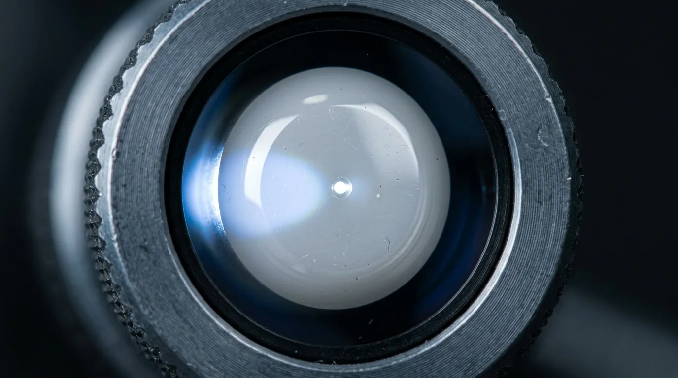
End-face cleanliness criteria. Cleaning and inspecting before mating is not folklore; it has a standard with quantitative zones and limits. IEC 61300-3-35 specifies how to assess the end face of a polished connector — scratches, debris and defects — across the fiber zones and the full contact area, and even sets minimum requirements for the microscope used to judge it. It also notes that a connector cannot be rejected on a failed visual inspection alone, which matters when you are writing an acceptance procedure: the inspection is a screen, and the loss measurement is the verdict.
The cleaver is the cheapest place to buy performance in the whole termination process. Blade condition, not connector grade, is the variable a field crew can change for the least money — and it is the one that decides how often a splice has to be cut back and remade.
Two standards govern those figures, and they are the ones to ask a supplier to cite. IEC 61753-1 and IEC 61754-4 are the interface and performance references that appear on real assembly datasheets, alongside the applicable GR-series documents — GR-326 for single-mode connectors and jumper assemblies, and GR-3120/GR-3152 for weatherized outdoor assemblies. Ask a supplier to cite the exact document number and revision rather than a family name. A supplier who quotes insertion loss without naming the test standard, the wavelength and the sample size has told you nothing you can put in a specification — our own guide to the difference between insertion loss and return loss covers how each is measured and where the two are confused.
One supplier's published range, for reference. The table below is DYS's own datasheet range for its own products — a worked example of what a datasheet entry contains, not a neutral industry benchmark. Treat any supplier's table, including this one, as a claim to be checked against measured per-assembly data.
Assembly (DYS range) | Loss (typ. / max) | Return loss | Datasheet check |
|---|---|---|---|
DYS LC Fast Connector, SM-UPC | ≤0.10 / ≤0.35 dB | ≥45 dB | 500 mating cycles, −40 to +85 °C |
DYS SC Fast Connector, SM-APC | ≤0.15 / ≤0.35 dB | ≥55 dB | IPSCAPC waterproof variant rated IP68 |
DYS 4-in-1 Universal SC, SM-APC | ≤0.15 / ≤0.30 dB | ≥60 dB | IP68, IEC 61753-1 / IEC 61754-4 |
DYS FTTH round patch cord, SM-APC | ≤0.15 / ≤0.30 dB | ≥60 dB | GR-1320, IEC 61753-1 / IEC 61754-4 |
The Splice Workflow: Eight Steps from Bare Fiber to a Tested Termination
The workflow below assumes a single-mode fusion splice inside an ODF, tray or closure. It is the same sequence whether you are terminating 1 fiber or 12 — the bundle just changes how many times you repeat steps 2 through 8.
1. Route cable and set slack. Bring the cable into the enclosure and leave enough slack to reach the tray, plus one re-splice attempt. Pass: every fiber can reach its assigned splice position without tension. Failure mode: insufficient slack, discovered after the splice is made, forcing a second splice to extend the pigtail.
2. Strip and clean the fiber. Remove the jacket and buffer to the required length — long enough to reach the splice protector and tray, short enough to avoid a tangle. Pass: clean, undamaged bare fiber with no residual coating. Failure mode: a nick from the stripper that survives until it snaps inside the tray.
3. Cleave. Precision, repeatable cleaves are what buy you the 0.5 dB range instead of the 0.75 dB range. Pass: a flat, perpendicular end face with no lip or hackle. Failure mode: a contaminated or worn cleaver blade producing a chip — visible on the splicer screen, and the single most common cause of a failed first splice.
4. Prepare the tray. Lay out the pigtails and the incoming cable so the routing order matches the port numbering before you make any splice. Pass: each pigtail can be coiled to its final position without crossing another. Failure mode: splicing in cable order instead of port order, producing a 12-fiber tray that is physically correct and logically scrambled.
5. Fuse. Load both fibers, run the arc, and read the splicer's estimated loss. Every modern splicer estimates splice loss and tells you whether to remake the splice. Pass: estimated loss within your acceptance threshold, accepted on the operator's own judgement — not on the assumption that the machine is right. Failure mode: accepting a marginal splice because the splice count in the tray is already high.
6. Protect the splice. Apply a heat-shrink splice protector (or clam-shell protector) over the joint and let it cool fully before moving anything. Pass: protector fully shrunk, no bubbles, fiber not pulled. Failure mode: coiling the fiber while the protector is still soft, which introduces microbending you will find months later on an OTDR trace.
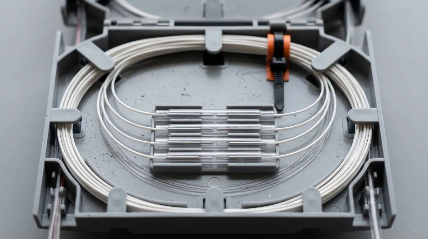
7. Coil and dress. Route the pigtails into the tray within the manufacturer's minimum bend radius and secure them so nothing can migrate when the closure is closed. Pass: coils flat, consistent, and inside the tray's stated capacity. Failure mode: overfilling the tray. Bend loss is quiet justification for a specification that names a bend-insensitive fiber type; where long-term bending stress is expected, ITU-T G.657 bend-insensitive single-mode fiber tolerates tighter routing than standard G.652.
8. Test and record. Measure end-to-end loss in both directions, keep the trace files, and label each strand using the TIA-598 color code sequence so the next technician can identify fiber 7 without opening the tray. Pass: every strand within budget, with a record tying each measurement to a labeled fiber. Failure mode: commissioning on a single-direction measurement and inheriting an unexplained loss that nobody can localize later.
Step | Pass looks like | Common failure, and what it costs |
|---|---|---|
1 Route & slack | Every fiber reaches its position with room to re-splice | No slack → second splice → two splices in the budget |
2 Strip & clean | Clean bare fiber, no nicks | Stripper nick → delayed snap inside the tray |
3 Cleave | Flat, perpendicular end face | Worn blade → rejected splice, repeated cleaves |
4 Tray preparation | Routing order matches port numbering | Spliced in cable order → logically scrambled tray |
5 Fuse | Estimated loss inside threshold, remake if not | Marginal splice accepted → permanent budget hole |
6 Protect | Protector shrunk, cooled, undisturbed | Moving a hot protector → microbend loss |
7 Coil | Inside bend radius, within tray capacity | Overfilled tray → bend loss and future faults |
8 Test & record | Bi-directional loss + labeled strands | One-way test → an unexplainable loss on the next visit |
The fusion splice workflow for fiber optic cable covers the splicing equipment itself in more depth.
For instrument choice, referencing and what a clean trace looks like, see the test and measurement procedure.
Pigtail vs Field-Installable Connector: Where Each One Wins
A field-installable connector — the fast connector family — does the opposite of a pigtail. Instead of polishing an end face in the factory and splicing onto bare fiber, it carries a factory-polished ferrule with an embedded fiber stub, and a mechanical splice cavity inside the body. You strip, cleave, insert and lock. No fusion splicer, no heat, no polishing. The question worth answering is not which is better but where each one earns its place.
Dimension | Pigtail + fusion splice | Field-installable connector |
|---|---|---|
Loss control | Factory end face + a splice the machine verifies and can remake | Factory end face + a mechanical splice that cannot be re-verified on site |
Entry cost | Fusion splicer, electrodes, consumables (capital) | Per-unit consumable, almost no entry cost |
Cost per termination | Falls with volume; usually wins above roughly a dozen fibers per enclosure (rule of thumb) | Roughly flat; wins on single drops and low counts |
Rework | Splice can be opened, remade and re-protected | Cut off and replace |
Skill floor | Machine, arc parameters per fiber type, operator judgement | Strip, cleave, insert, lock |
When it is tested | Splicer estimate, then link test | Link test, after the assembly is installed |
Best fit | Central office, ODF, closure, multi-fiber bundles | Single-drop activation, repair, confined access, no splicer on site |
Insertion loss and return loss. Both approaches carry a splice-like interface inside them, so both pay a two-part loss. The difference is control. A fusion splice can be verified by the machine that made it and remade on the spot; a mechanical splice inside a connector cannot be re-verified without instruments. Pigtail + fusion splice wins where the loss budget is tight or where every dB at 400G-era spacing is contested.
Cost structure. This is the dimension that flips most often. A fusion splicer is a capital purchase plus consumables, electrodes, and a calibration habit. A field-installable connector is a per-unit consumable with a low entry cost. If you are terminating a handful of fibers at a customer premises, the connector wins on total cost every time. If you are terminating hundreds of fibers in a central office or closure, the splicer amortizes within the project and the pigtail wins on both cost per termination and consistency.
Environment and rework. Field-installable connectors are available weatherized — the DYS IPSCAPC fast connector is rated IP68 at 1 m for 1 hour with a max insertion loss of 0.4 dB, and the same family covers LC, SC and FC. That makes a waterproof fast connector a legitimate answer for an outdoor drop repair. Inside an ODF, a mechanically spliced connector's weakness is that it is not inspectable and not reworkable without cutting it off — while a fusion splice can be opened, remade and re-protected.
Crew skill and training curve. Field-installable connectors reduce the skill floor: a technician who can strip and cleave correctly can terminate a working connector on the first attempt. Fusion splicing adds a machine, a set of arc parameters for each fiber type, and an operator who reads the splicer's estimate as information instead of decoration. Small teams and repair crews are usually better served by the connector.
Testing burden. A pigtail splice is tested by the splicer and then by the link tester. A mechanically spliced connector normally gets its first real measurement at link test, when the assembly is already installed and hard to replace. Where access is difficult, that asymmetry matters more than the nominal loss figures.
Scalability. A 12-fiber bundle is one cleaving session and twelve machine cycles. Twelve field-installable connectors is twelve individual field terminations, each with its own cleave quality and its own risk. Above roughly a dozen fibers in one enclosure, pigtails win on time and consistency; below it, the connector's low entry cost usually dominates. That crossover is a rule of thumb rather than a measured threshold — it moves with splicer and connector pricing.
A third option sits between them. Splice-on connectors (SOCs) put a factory-polished ferrule on the end of a connector and attach it with a fusion splice instead of a mechanical one — the FOA's reference on splice-on connectors walks through both variants. You get the factory end face and the verified splice, and you still pay for the splicer. That is the option to consider when you want pigtail-class optical performance but the cable cannot be routed into a tray.
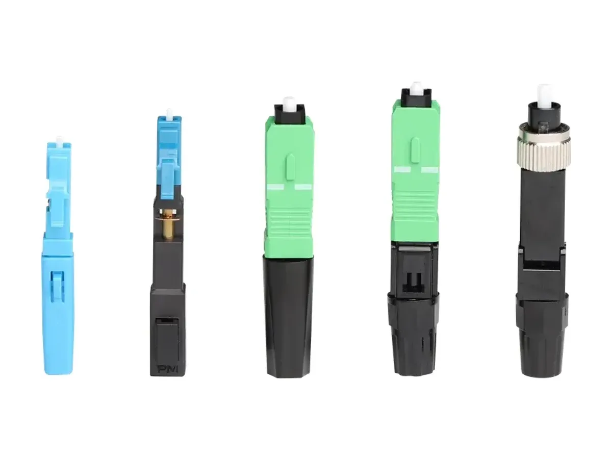
When the field-installable connector is the better choice — and this is a real recommendation, not a courtesy paragraph: single-drop FTTH activation and repair, terminations in confined or elevated locations where a splicer cannot be set up safely, projects with no splicer on the crew, sites where the fiber count is low enough that the splicer's capital cost never amortizes, and situations where a fast turnaround matters more than the last fraction of a dB. A field-installable fast connector that terminates in minutes and tests inside the 0.75 dB TIA-568 ceiling is a better engineering decision than a perfect splice nobody on site is equipped to make.
The fast connector range is the product family for that scenario — LC, SC and FC bodies, no injection or grinding, with 500 mating cycles of durability. DYS manufactures it alongside its jumper assembly and waterproof assembly lines in the same factories, so both sides of this decision come from one supply chain rather than two.
How to Choose Fiber Pigtails: A Decision Order, Not a Feature Race
Buyers tend to compare components. The decision is better made as a sequence, where each step eliminates options before the next one starts.
1. Environment and enclosure first. Where does the termination physically live — indoor ODF, sealed closure, hand-hole, tower-top? Anything with standing water or continuous UV exposure takes a weatherized assembly out of the standard indoor catalog. This single question eliminates more SKUs than any other.
2. Fiber count per location. Count the fibers terminated at that enclosure, not the fibers in the project. This is the step that decides pigtail versus field-installable connector, and it is the step most often skipped.
3. Loss budget headroom. Add up the existing allowance for connectors and splices across the link and see what is left. If the headroom is thin, the pigtail's verifiable splice is worth paying for. If there is room, the cheaper termination is not a compromise.
4. Crew skill and equipment. Does the team have a splicer, electrodes, and an operator who interprets the splice estimate? If not, either buy that capability or specify a connector that works without it — but decide deliberately, not by default.
5. Test and acceptance regime. Decide before installation how the work will be accepted: bi-directional loss, trace retention, per-strand labeling. The acceptance regime determines which termination method is practical. Where a connector cannot be re-measured after installation, plan the measurement before, not after.
6. Compliance and origin. Match the certification set to the destination market and keep the paperwork. This last step filters suppliers rather than components, and it is the one that determines whether the shipment clears.
Decision step | Look at | Eliminates |
|---|---|---|
1 Environment | Indoor / sealed / outdoors / tower | Anything not rated for the location |
2 Fiber count | Fibers terminated in this enclosure | Splice vs field-installable connector |
3 Loss headroom | Remaining dB in the link budget | Cheaper terminations with unverifiable loss |
4 Crew and equipment | Splicer availability and operator skill | Methods you cannot actually execute |
5 Acceptance regime | How the work is tested and recorded | Methods that cannot be re-measured |
6 Compliance and origin | Destination market, certification set | Suppliers who cannot document the product |
The sequence matters because it runs from the constraint you cannot change to the one you can. Teams that start at step 6 and work backwards end up choosing a supplier first and a component second — which is how a project ends up with mechanical splices where fusion was the right call, or the reverse.
What to Ask a Supplier Before You Approve the Batch
Pigtails are cheap per unit and expensive when a batch is wrong, because the cost lands at installation, not at goods-in. Seven items on a request-for-quote turn a hopeful purchase into a controlled one.
1. Per-assembly insertion loss and return loss data at named wavelengths. Not a catalog maximum — measured values with the wavelength and sample size stated.
2. End-face inspection results with the criteria named. If the supplier inspects to IEC 61300-3-35, the report tells you what was measured and against which limits.
3. The color-code sheet and identification chart. For bundles of 6, 12, or more, confirm the sequence follows TIA-598 and that the chart ships with the goods. A bundle without an identification chart costs handling time at every future fault.
4. Construction and environmental rating in writing. Tight buffer diameter, jacket material, minimum bend radius, IP rating where applicable, and the temperature range for operating and installation.
5. Standards cited by number. A supplier should be able to name the interface and performance standards their assembly is tested against, for example IEC 61753-1 and IEC 61754-4, plus the applicable GR-series documents for weatherized assemblies.
6. Sample evaluation and retained samples. Terminate a sample batch, measure it with your own instruments, and keep the samples so the production batch has something to be compared against.
7. Certification set for the destination market and the manufacturing origin. UL and OFNP for the United States, CPR for the European Union, ANATEL for Brazil, alongside ISO 9001 and TL 9000 for the quality system — and a clear statement of where the goods are made. Origin is a commercial variable, not a footnote: a supplier with manufacturing in more than one country gives a buyer somewhere to go when tariffs or logistics change.
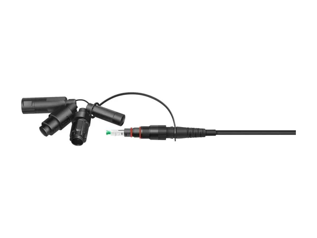
DYS Fiber Optic has manufactured fiber connectivity hardware since 2009, with factories in Huizhou, Mianyang and Vietnam and a portfolio that includes indoor cable used for pigtailing, FTTH patch cords and drop jumpers, weatherized connectors and terminal boxes — 100% pre-shipment testing under an ISO 9001 system, with IL/RL test data available on request. If you are building a specification for an FTTH or access-network rollout, request a sample or a quotation and evaluate it against the seven items above rather than against a catalog figure.
The decision reduces to something simple. A pigtail sells you a factory end face and asks you to make one splice well; a field-installable connector sells you speed and asks you to accept a splice you cannot inspect. Determine the environment and the fiber count first, then pick the termination that fits — and write both the connector loss and the splice loss into the budget, because the link will charge you for both.