

Connectors
Fiber Fast Connectors: Field Termination for FTTH
Every FTTH rollout hits the same bottleneck: the last few meters. The drop cable arrives at the subscriber's home, and somebody has to terminate it — cleanly, quickly, and without a truck roll coming back next week. Fiber fast connectors were built for exactly this job. They are field-installable connectors that terminate a single fiber in minutes using nothing more than a stripper, a cleaver, and the connector itself — no fusion splicer, no epoxy, no polishing. That combination is why they dominate FTTH drop termination in markets where deployment speed decides project economics.
This guide covers what a fast connector is and how it works, when it beats fusion splicing and pre-terminated pigtails, the step-by-step installation procedure, how to pick the right SC, LC, UPC, or APC variant for your drop cable, and how to verify the termination before you walk away.
What Is a Fiber Fast Connector?
A fiber fast connector is a mechanical, field-installable termination for single-fiber cables. Inside a compact SC, LC, or FC body, it holds a factory pre-polished ferrule and a mechanical splice mechanism. You insert a cleaved fiber end into the connector body; the splice mechanism aligns it against the polished fiber stub already embedded in the ferrule, and a clamp or cam locks it in place. Light crosses from your drop fiber to the stub through the polished interface — no heat, no adhesive, no grinding.
Three design choices define how fast connectors behave:
- Pre-polished ferrule. The critical optical surface is made in the factory, under controlled conditions, instead of in a van or on a ladder. This is what removes hand polishing from the job.
- Embedded fiber stub. The connector carries its own short fiber stub inside the ferrule. Your drop fiber butts against it inside the mechanical splice cavity. This embedded-fiber design is why a fast connector is typically a single-use (or limited-reuse) component — the splice cavity wears slightly with each termination.
- Mechanical alignment. Index-matching gel in the splice cavity reduces the reflection at the fiber-to-stub interface, and a clamping mechanism holds the fiber securely against vibration and temperature swings.
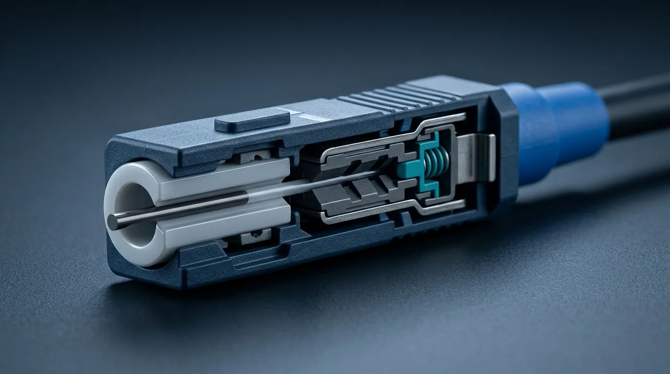
Anatomy of a field-installable fast connector: the factory-polished ferrule, the embedded fiber stub, and the splice cavity where the drop fiber is locked in place.
The payoff is measurable. A competent technician terminates a fast connector in roughly two to five minutes including preparation, versus ten to fifteen minutes for epoxy-and-polish termination and more when the fusion splicer has to be unboxed and warmed up. The trade-off is optical performance: a fusion splice typically lands at 0.02–0.05 dB insertion loss, while a fast connector typically lands in the 0.1–0.5 dB range depending on design and polish grade — the same envelope documented by field-installable series like Fujikura's FAST connector line, which quotes average connection loss of 0.5 dB or less. For a subscriber drop running 100–500 meters, that difference is invisible to the service — and it buys a dramatically cheaper, faster installation.
Fast connectors are available in the same interface formats as conventional connectors, so they plug into existing adapters and equipment without any network-side change. The pre-polished ferrule at the heart of the design is the same approach used by every major field-installable line, from AFL's FASTConnect mechanical connectors to Corning's UniCam family. The complete picture of how these formats fit together — ferrule sizes, coupling mechanisms, polish grades, and where each type is used — lives in our fiber optic connector guide, the hub for this topic. The short version for drop work: SC is the FTTH workhorse, LC appears where density matters, and APC polish is the default for GPON.
Fast Connector vs. Fusion Splicing vs. Pre-terminated Pigtail
Fast connectors do not replace splicing everywhere — they replace it in a specific slice of the network. Choosing wrong costs either too much labor (splicing every drop) or too much loss (fast-connecting a backbone). Here is the honest comparison table:
Method | Typical IL | Install time | Tools required | Best suited for |
|---|---|---|---|---|
Fusion splice | 0.02–0.05 dB | 3–8 min incl. setup | Fusion splicer + cleaver + protection sleeve | Backbone, distribution, high-density, anything needing lowest loss |
Fast connector | 0.1–0.5 dB | 2–5 min | Stripper + cleaver + connector | FTTH drops, repairs, low-density field termination |
Pre-terminated pigtail | 0.1–0.3 dB (splice at far end) | 1–2 min to install | Fusion splicer for the far end | Indoor ONT areas, patch panels, MDU risers |
Three rules of thumb fall out of this table:
- Use fast connectors on the drop. The subscriber drop is short, single-fiber, and terminated in unpredictable locations (attics, façades, street cabinets). A fast connector puts the termination where the drop lands, with no splicer on site.
- Use splicing where loss and density are the product. Splitters, distribution frames, and risers are usually terminated by fusion because the fiber count is high and the loss budget is already tight. The mechanics and tolerances of splice work are covered in our guide to splicing fiber optic cable.
- Use pre-terminated assemblies where you can. Factory-terminated pigtails and patch cords are the cheapest, most consistent option whenever you can plan the length ahead of time — but they require a splice or a connector at the end anyway, which is exactly the step fast connectors compress.
One more consideration is repair. When a drop fiber breaks at the subscriber side — a staple through the cable, a door hinge, a rodent — a fast connector turns a repair into a 10-minute visit with a hand kit. That is the single strongest argument for carrying fast connectors in every FTTH installation van, even on projects that splice everything else. The mechanical splice principle behind them is the same technology described in the overview of fiber mechanical splices, adapted into a connector housing.
How to Install a Fiber Fast Connector: Step by Step
The procedure varies slightly between designs, but every fast connector on the market follows the same six stages. Practice on a scrap length before you do it on a subscriber's cable.
Step 1 — Prepare the cable. Strip the outer jacket back to expose the bare fiber. For a flat drop cable (the 2.0 × 3.0 mm butterfly style common in FTTH), strip roughly 30 mm of jacket, remove the strength members, and clean the bare fiber with an alcohol wipe. Do not touch the cleaned fiber with bare fingers — oils degrade the splice.
Step 2 — Cleave the fiber. Insert the fiber into a high-precision cleaver and cleave at the length specified for your connector (typically 8–12 mm for the fiber stub). The cleave quality is the single biggest factor in final loss. If the cleave is chipped or angled visibly, re-cleave — a bad cleave that "looks close enough" is how 0.8 dB terminations happen.
Step 3 — Open the connector. Remove the dust cap from the rear of the connector and open the clamp or cam mechanism. Some designs use a wedge you slide out, some use a flip-open housing. Do not touch the ferrule end face.
Step 4 — Insert the fiber. Push the cleaved fiber into the splice cavity until it seats against the fiber stub. You will usually feel a stop or see a marker window. Inserting too shallow leaves an air gap (high loss); too deep can damage the stub face (high loss and reflections). The marker window on the connector body shows you exactly how far in the fiber has traveled — use it.
Step 5 — Lock the mechanism. Close the clamp, cam, or crimp per the manufacturer's instructions. This mechanically holds the fiber against the stub. A connector that is not fully locked will drift in loss as the cable moves.
Step 6 — Verify, don't assume. Attach the terminated connector to the drop and check the link before you close up the enclosure. At minimum, shine a visual fault locator (VFL) through it — red light leaking at the connector body means a bad insertion. If you have an optical power meter and source, measure the actual insertion loss. Details on both methods are in the testing section below.
Common mistakes that quietly produce failed terminations: skipping the alcohol wipe, reusing a connector after a failed insertion (the splice cavity is contaminated by then), and terminating without checking the cleave angle. If a termination fails, cut the fiber back, re-cleave, and use a fresh connector — do not try to reset a used one.
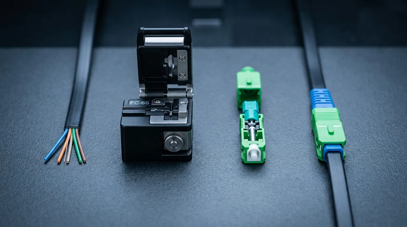
The full termination sequence: strip the jacket, cleave the fiber, open the connector, insert to the marker, lock the mechanism, then verify the link.
The full field procedure for the surrounding work — cable prep, enclosure handling, and test methodology — is covered in the fiber optic installation field handbook.
Choosing the Right Fast Connector: SC vs. LC, UPC vs. APC, and Drop Cable Fit
Fast connectors come in the same format families as conventional connectors — the families cataloged in the Wikipedia overview of optical fiber connectors — and the choice is driven by the network you are terminating into, not by the connector itself. If you need to refresh the fundamentals — ferrule sizes, body shapes, and locking mechanisms — our guide to fiber optic connector types walks through identification by sight. For drop work specifically, three decisions matter:
1. Interface: SC or LC? SC is the default for FTTH. Its 2.5 mm ferrule and push-pull body take rough handling and mate easily in tight enclosures, and SC/APC is the standard port on GPON ONTs and OLTs. LC fast connectors exist for networks that standardize on the smaller 1.25 mm format — typically enterprise or multi-operator premises where LC is the common denominator. If your deployment standard is SC, do not buy LC "because they look modern"; buy what matches your ONT and OLT ports.
2. Polish: UPC or APC? This is the decision with the biggest performance consequence. APC (green) ferrules are angled at 8 degrees, which pushes reflected light out of the fiber core; they deliver return loss of 55 dB or better. UPC (blue) ferrules are flat-polished and return 45–50 dB. APC is required on PON drop links — GPON receivers are sensitive to reflections, and mixing an APC connector with a UPC adapter or vice versa damages the angled ferrule faces. The color coding (green = APC, blue = UPC) makes the mismatch visible at a glance — check the polish against your ONT and OLT ports before you order, not after you terminate 500 drops with the wrong variant.
3. Cable fit: does the connector match your drop cable? This is the most commonly overlooked spec. Fast connectors are built for a cable diameter range, and the range is printed on the spec sheet for a reason. FTTH flat drop cables (2.0 × 3.0 mm butterfly) need connectors with a matching slot profile; round drop cables take 2.0 mm or 3.0 mm variants; some outdoor designs accept the larger 5.0 mm jacketed cables. Ordering a connector for a cable it was not designed for produces loose clamps, fiber strain, and field failures months later. If you are choosing or spec'ing the drop cable itself, the FTTH drop cable guide covers flat, self-supporting, and round options and how they match field hardware.
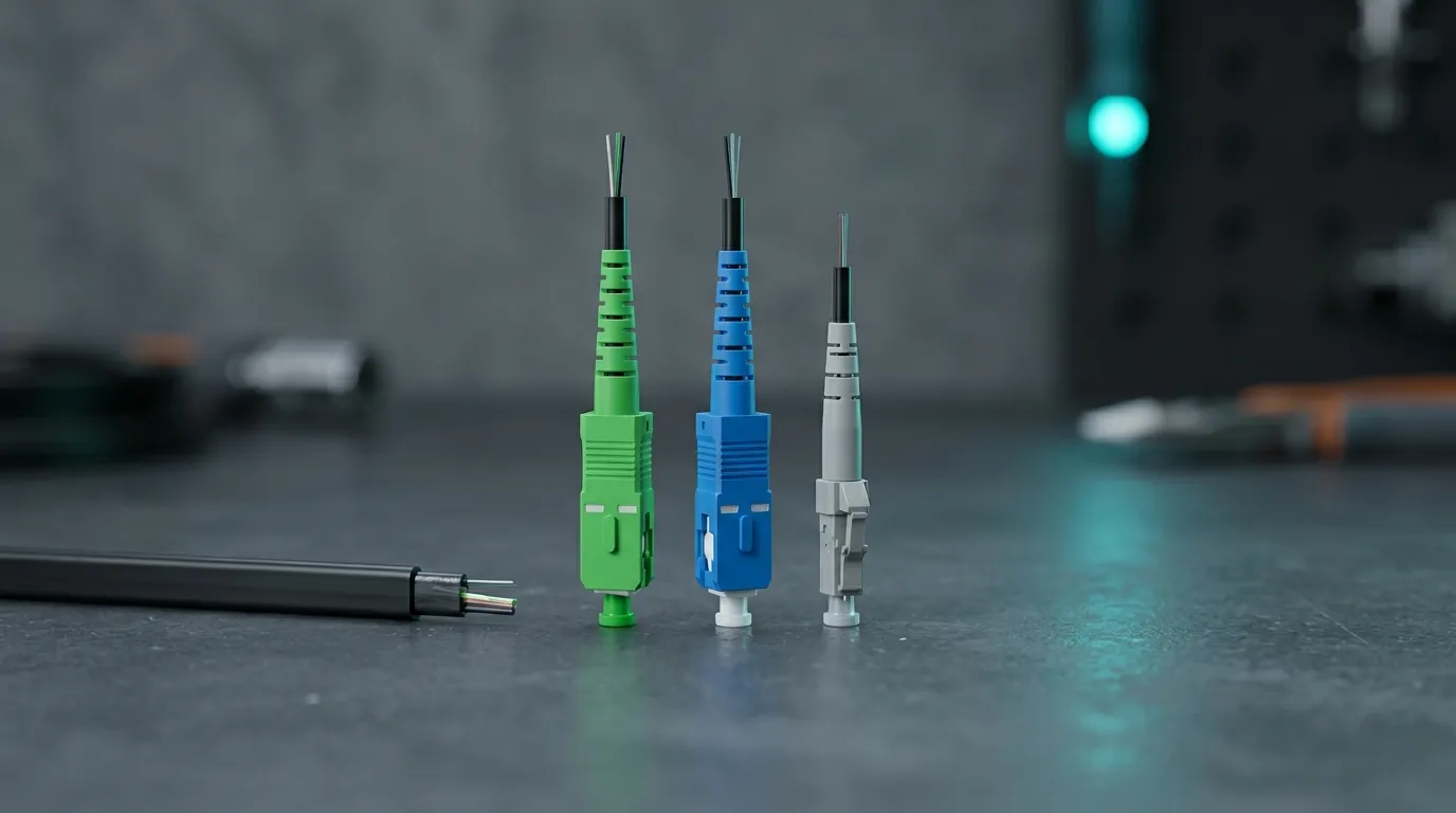
Selection matrix: interface, polish, and cable fit are three independent decisions — lock all three before you buy.
One practical note: buy your fast connectors and your drop cable from sources that test them together. A manufacturer that produces both — DYS, for example, builds its fast connector family in SC, LC, and FC formats specifically to match its flat and round drop cable range — can tell you which connector part number pairs with which cable construction. That pairing, documented on paper, is worth more than any spec sheet comparison.
When Not to Use a Fast Connector
Every technology has a boundary, and fast connectors have a clear one. Do not use them:
- In high-fiber-count distribution. Splitting 32 or 64 fibers in a cabinet with fast connectors multiplies both loss and failure risk. Fusion splicing is the right tool where loss budget and density matter.
- On long backbone or trunk links. A 0.5 dB worst-case connector adds up fast across a 10 km link. Splice it.
- Where the termination is made once and then left in a protected indoor spot. If the fiber terminates next to the ONT anyway, a factory pigtail fused in place is lower loss and lower cost per termination at volume.
- Where return loss is critical and the link is analog or RFoG. The higher reflectance of a mechanical interface can degrade analog video and RF-over-Glass signals. Use fusion splices or high-performance factory terminations there.
- In repeated-remate environments. Fast connectors are designed to be terminated and then mated to an adapter — they are not patch-cord connectors meant for hundreds of mating cycles. For frequent reconnects, use factory patch cords.
This boundary is also a planning signal. When a rollout includes a mix of drops, risers, and MDU distribution, the smart plan separates the methods by segment — fast connectors on the drop, fusion in the riser. Our guide to FTTH MDU deployment walks through exactly that segmentation for multi-dwelling buildings, where the termination method decision has the biggest cost impact per subscriber.
How to Verify a Field Termination
A fast connector that looks installed is not the same as a fast connector that works. Budget two minutes of verification into every termination, because a silent failure here becomes a truck roll later.
Minimum check — the VFL test. Connect a visual fault locator to the far end of the drop (or shine into the terminated connector). Red laser light should appear only at the fiber core on the far end. If you see a bright red glow at the connector body or along the splice cavity, the termination is leaking — the fiber is misaligned, the cleave was bad, or the mechanism was not fully locked. Re-terminate.
Proper check — insertion loss measurement. Use an optical light source and power meter (OLTS) at the working wavelength (1310 nm and 1550 nm for single-mode PON). Measure the drop end to end and subtract the known loss of the cable itself. A healthy fast connector termination contributes roughly 0.1–0.5 dB; if the measurement is higher, re-terminate and measure again. For PON, the total link budget from OLT to ONT — including splitter loss — is what the network was engineered against, so a few tenths of a dB per drop matters at scale.
Return loss check (when the spec demands it). If your deployment requires APC-grade return loss (55 dB class), the connector must carry the corresponding APC polish — and the measurement only confirms what the polish already implies. A green ferrule with a flat polish face is a factory defect, not a field fix.
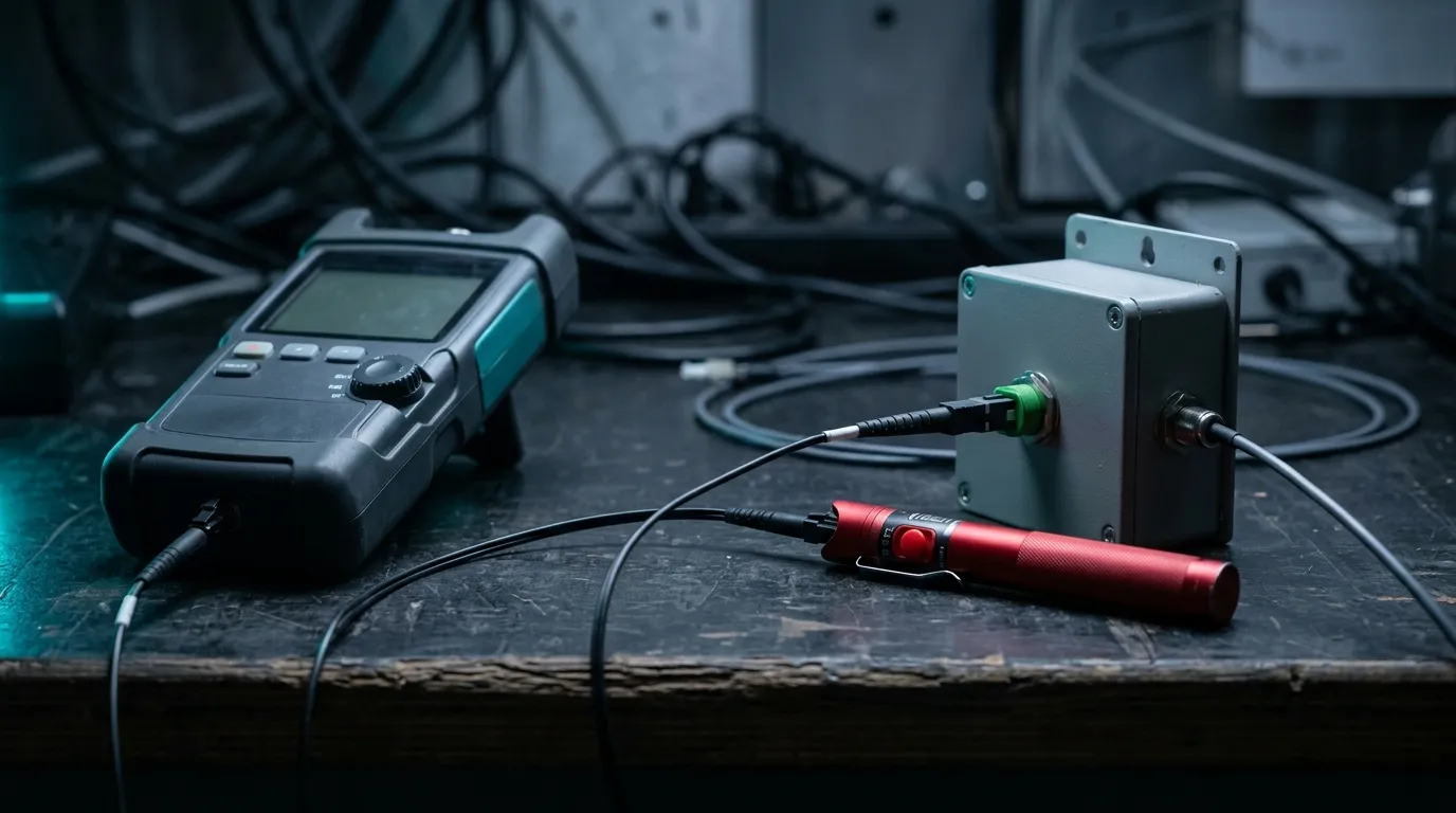
Verification kit: a VFL catches gross failures in seconds; a source and power meter quantify the termination's insertion loss.
Keep the test record per drop: cable ID, connector part number, cleave and insertion timestamps, measured loss. In a rollout of thousands of drops, that record is what lets you find the 2% of bad terminations before the subscribers do — and it is what an operator audit will ask for.
What to Check When Sourcing Fast Connectors in Bulk
If you are buying fast connectors by the thousand for a rollout — or sourcing them for a deployment program — the spec sheet does most of the screening work, but only if you read the right lines. This is the checklist we use when qualifying any connector line:
- Insertion loss and return loss, worst-case, not typical. A sheet that quotes only "≤0.1 dB typical" is hiding the max. Look for both typical and maximum; field terminations live at the max end. For SM-APC drop connectors, expect max IL ≤0.35 dB and RL ≥55 dB; for SM-UPC, RL ≥45 dB.
- Mechanical endurance. 500 mating cycles is a reasonable floor for a connector that will be mated and unmated during installation and maintenance. Fewer than 200 suggests a disposable-grade part.
- Environmental range. FTTH hardware sits in attics, façades, and street cabinets. The operating range should cover −40 to +85 °C; anything narrower will show up as seasonal failure clusters. For aerial or exposed outdoor drops, look for an IP-rated waterproof variant (IP68 class) rather than a plain indoor connector.
- Cable compatibility list. The sheet must state which cable diameters and jacket profiles the connector accepts — and your drop cable must be on it. If the vendor cannot name the cable construction the connector was tested with, treat the pairing as unverified.
- Standards alignment. Reference documents such as GR-1320, IEC 61753-1, and IEC 61754-4 define performance and interface requirements for connector families. A vendor that cites them can usually show you the test data behind the citation.
- Reusability policy. Some designs tolerate a second termination attempt; most do not. Know which one you are buying so the field team does not try to reset a used connector and produce a marginal link.
For reference, a healthy spec envelope for FTTH drop fast connectors looks like this:
Parameter | Healthy value | Why it matters |
|---|---|---|
Insertion loss (max) | ≤0.35 dB (SM) | Worst case, not typical, is what field terminations land at |
Return loss (min) | ≥45 dB UPC / ≥55 dB APC | Reflections directly hurt PON receivers |
Mating durability | ≥500 cycles | Survives installation, testing, and maintenance remates |
Operating temperature | −40 to +85 °C | Attics and street cabinets swing far outside indoor ranges |
On the outdoor half of the FTTH network — aerial self-supporting drops and ground-duct runs — the termination often sits in a waterproof closure or terminal box, where an IP68-rated fast connector (like the DYS IPSCAPC line, built for flat-cable aerial and duct applications) removes the separate waterproofing step. If your drop segment is exposed, price that variant into the bill of materials from the start rather than retrofitting covers later.
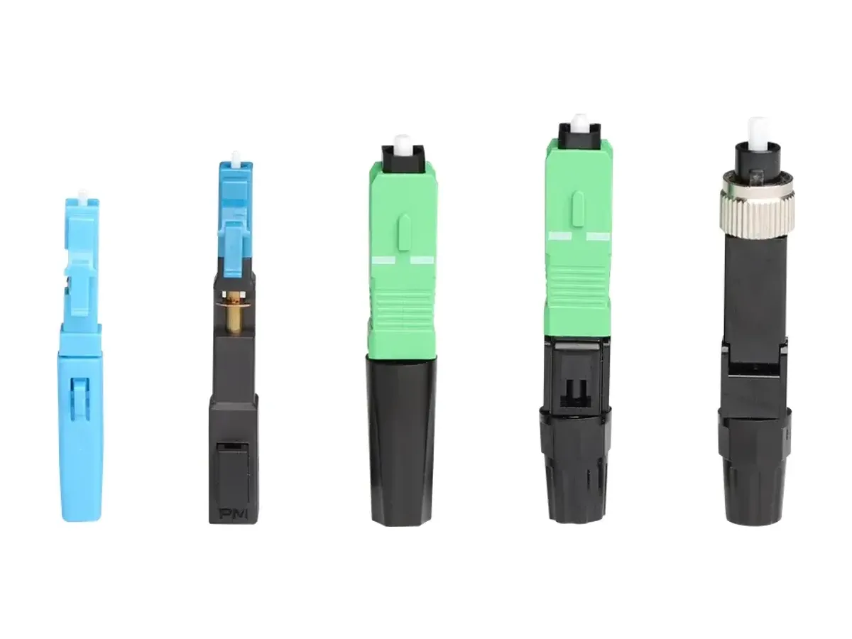
A factory fast connector family in SC, LC, and FC formats — the same pre-polished design terminates flat, round, and self-supporting drops.
Buying from a single manufacturer that produces the drop cable, the fast connector, and the enclosures also simplifies one thing no spec sheet covers: accountability. When the cable and the connector come from the same factory, the cable-connector pairing is tested as a system, and a field failure has exactly one vendor to answer for it. If you are evaluating a supplier for a rollout, our FTTH deployment guide covers the full last-mile stack — drop cables, splitters, terminal boxes, and termination hardware — in one place. And when you are ready to compare fast connector samples against this checklist, our engineering team will send you matched cable-and-connector sample kits for testing — request samples with your drop cable spec and we will quote the matching connector line.