
Cable Selection
Fiber Optic Patch Cord Types: A Selection Guide
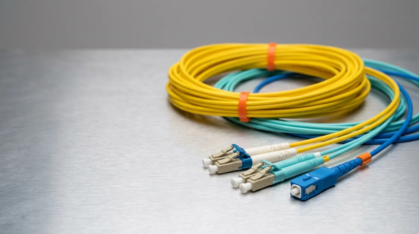
A fiber optic patch cord is a factory-terminated cable assembly with a connector on both ends, built to be plugged and unplugged rather than spliced. The connector interfaces are what most people mean by "patch cord types" — LC, SC, FC, ST, MPO — but the interface is only one of four independent axes that decide whether the assembly you order will actually work in the port you have.
Here is the number worth remembering before anything else: a patch cord is not one part number, it is four. Interface, polish grade, fiber count and mode, and cable construction are chosen separately, and getting three right while missing one produces an assembly that fits the port and still fails the link — the wrong return-loss grade on a video or RF-over-glass link, an APC plug forced into a UPC adapter, a duplex pair wired A-to-A in a row that expects A-to-B, or a riser-rated cord dropped into a plenum ceiling space where it is not legal to install.
This guide covers what a patch cord is and where it stops being one, why the familiar list of fiber optic patch cord types is only one axis out of four, the axes in the order worth specifying them, the loss and standard numbers that back each choice, the four steps to turn the axes into a single line item, and what to ask a supplier before you place the order. It is written for the people who have to write the specification — network engineers, integrators, and technical procurement — rather than for a product catalog.
What a Fiber Optic Patch Cord Is (and Where It Stops Being One)
A patch cord, a pigtail and a pre-terminated trunk are three answers to the same problem — "I need glass with connectors on it" — and they are not interchangeable:
- A patch cord is terminated at both ends, tested as an assembly, and used to connect equipment to equipment or equipment to a patching field.
- A pigtail is terminated at one end only; the bare end is spliced onto installed cable. If you are joining into a route, you want a fiber pigtails assembly, not a patch cord.
- A pre-terminated trunk is a multi-fiber assembly with a fan-out or a factory connector, pulled as a bundle between two points rather than patched in a rack.
"Type" is where the confusion starts, because vendors use it for whichever axis they happen to be selling. A page headed "types of patch cords" might be listing LC and SC (interface), or UPC and APC (polish), or simplex and duplex (fiber count), or riser and plenum (jacket). All four are real, and none of them substitutes for the others — which is exactly why this article's cable selection guide treats patch cords as a specification exercise rather than a product list.
The Four Axes: How to Read Any Patch Cord Spec
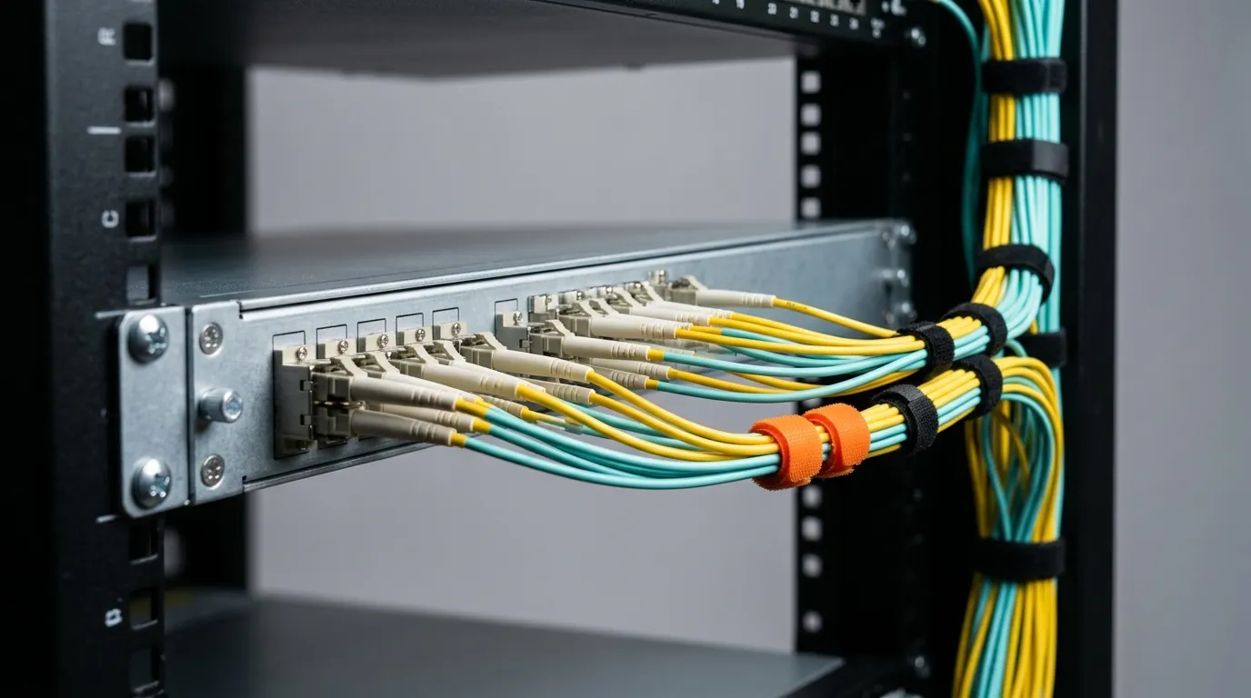
Every patch cord datasheet — and every list of fiber optic patch cord types you will find — is describing the same four axes. Read them in this order, because each one narrows the next.
Axis | The options | What it actually changes | Decide it by |
|---|---|---|---|
1. Connector interface | LC · SC · FC · ST · MPO/MTP (plus legacy MU, MTRJ, E2000, LX.5, SMA) | Ferrule diameter, footprint density, latch mechanism, mating durability | The port you are plugging into — this is usually fixed for you |
2. Polish grade | PC · UPC · APC | Return loss (reflectance) and whether the connector is keyed/angled | Wavelength, signal type, and whether the link is analog, RF or DWDM-adjacent |
3. Fiber count & mode | Simplex · duplex · multi-fiber; single-mode (OS2) · multimode (OM1–OM5) | How many paths the assembly carries, polarity, and which wavelengths and distances it supports | Transceiver type and reach |
4. Cable construction | Jacket material and fire rating (PVC · LSZH · OFNR/riser · OFNP/plenum) · armored · tight-buffer vs loose-tube · uniboot · breakout/fan-out | Where the cord may legally be installed, how much abuse it survives, and how it routes | The physical route: riser, plenum air space, tray, tower, or outdoor |
The mistake to avoid: specifying axis 1 and stopping, then discovering the incompatibility at commissioning. In practice the failures are almost never "wrong connector" — they are wrong return loss, wrong polarity, or wrong fire rating, all of which are printed on the part number in the last three positions and easy to skip.
Axis 1 — Connector Interface: LC, SC, FC, ST, MPO/MTP
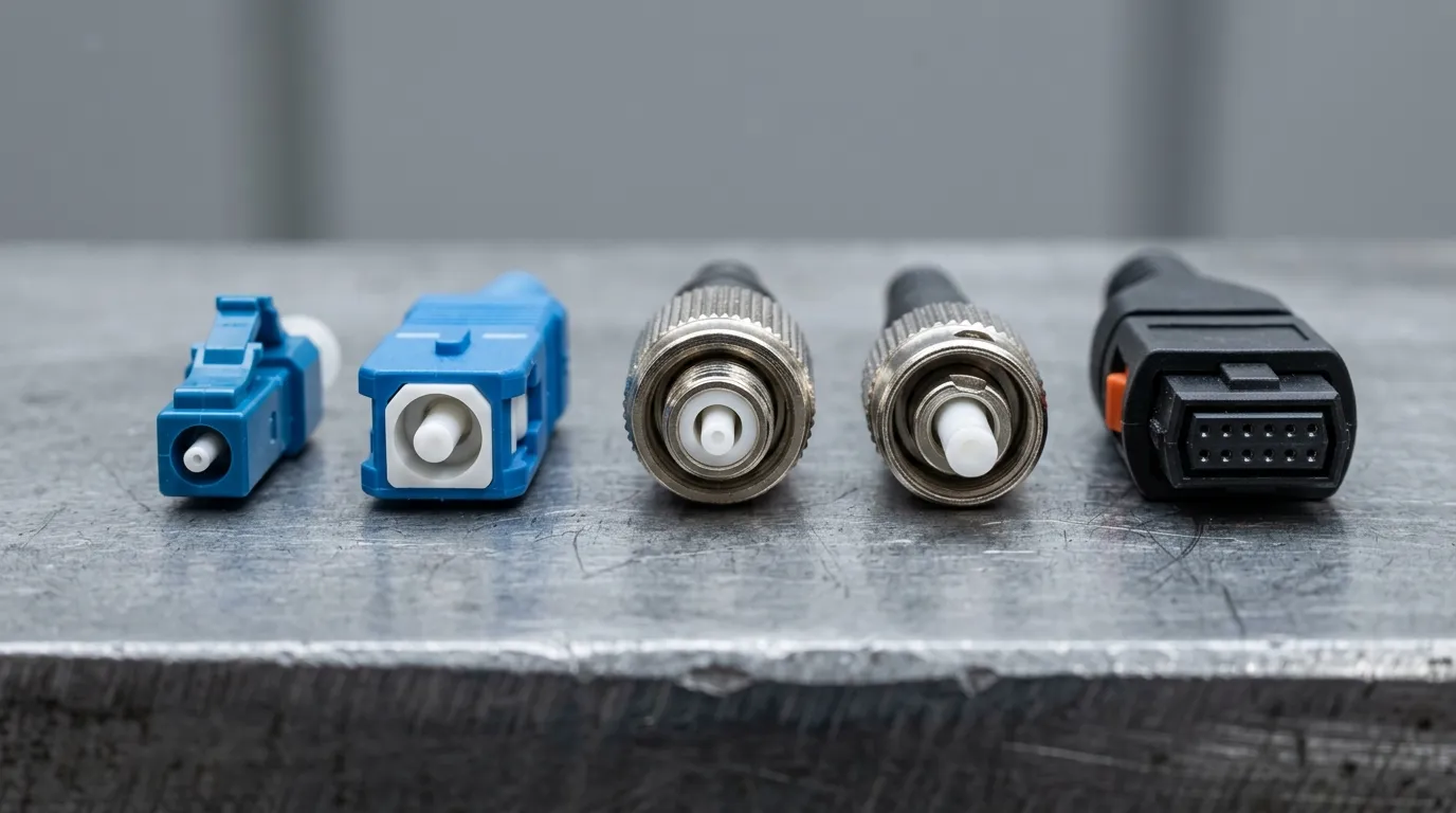
The interface is determined by the equipment port, so this is the least negotiable axis. What varies between families is ferrule size, latch design, and how many ports fit in a given panel.
Family | Ferrule | Latch / body | Notes that change a specification |
|---|---|---|---|
LC | 1.25 mm | Small plastic latch (RJ-style) | Highest density with SC-style performance; the default in modern SFP/QSFP ports; typically rated ~500 mating cycles |
SC | 2.5 mm | Square push-pull | The workhorse of patching fields, OLT/ONT and FTTH; typically rated ~1,000 mating cycles; usually the one to choose when density is not critical |
FC | 2.5 mm | Threaded, keyed | Still specified in test equipment and some legacy telecom gear; the screw coupling resists vibration but is slow to patch |
ST | 2.5 mm | Bayonet | Legacy LAN and industrial installations; being phased out, so specify only to match existing plant |
MPO/MTP | Multi-fiber (12/16/24) | Push-pull with guide pins | One plug carries 8–24 fibers; used for 40G/100G/400G parallel optics in data centers and as the backbone end of an MPO-to-LC breakout |
Ferrule diameter is the detail that makes the families physically incompatible: 2.5 mm in the SC, FC and ST camps and 1.25 mm in LC and MU, which is why the same nominal loss can sit behind very different durability budgets (connector reference, interface comparison). Around them sits a legacy family that is still in the field and still orderable — MU (1.25 mm, the original high-density Japanese interface), MTRJ (two fibers in one plastic body), E2000 and LX.5 (both with built-in shutters for laser safety, common on European carrier equipment), and SMA (905/906 threaded, found on older test sets and industrial links). None of these should be chosen for a new build, but "which one did our existing patch panel use" is a question worth answering before ordering replacements. Detail on the four main families is in the connector interface guide, and the head-to-head density and cost comparison is in LC vs SC.
Axis 2 — Polish Grade: PC, UPC and APC
Polish grade is the axis buyers skip most often and regret at cut-over. It sets return loss — how much light reflects back toward the transmitter — and it decides whether the end face is flat or angled.
Grade | End face | Typical return loss | Connector color convention | Where it belongs |
|---|---|---|---|---|
PC (physical contact) | Slightly domed | ~ −35 dB or worse | Beige/gray bodies (legacy) | Legacy multimode plant only |
UPC (ultra physical contact) | Domed, tighter tolerance | ≤ −50 dB (SM), ≤ −30 dB (MM) | Blue body | The default for digital links: Ethernet, FTTH, general patching |
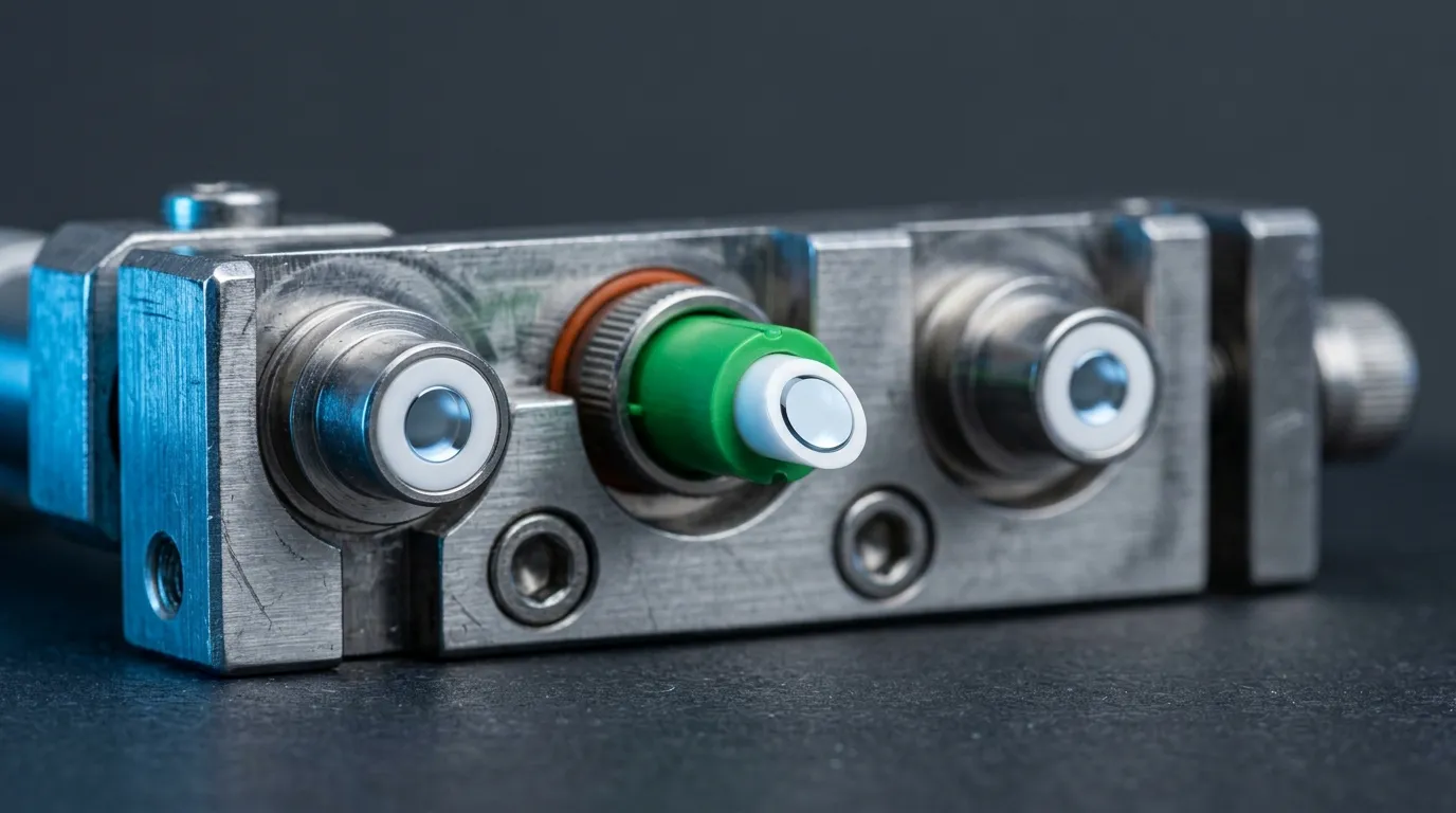
APC (angled physical contact) | 8° angled, usually green-bodied | ≤ −60 dB | Green body | Analog video/RF-over-glass, high-power or reflective-sensitive links, and the standard choice on FTTH access networks |
Two rules follow from the table. First, UPC and APC do not mix: an angled ferrule against a flat one loses contact area and produces both high insertion loss and high reflectance, and on some designs it can damage the tip. Match the polish of the port. Second, color is a convention, not a proof — the blue/green convention and the jacket color sequence come from TIA-598, and the surest verification is still reading the part number and the datasheet, not the boot (TIA-598 color codes). Return loss itself is defined and measured against the reflectance of the mated pair, which is why a good assembly datasheet states both the value and the wavelength it was measured at (return-loss reference).
If your link budget only tracks insertion loss, it is worth knowing that return loss is a separate line item that can fail a link on its own — the depth is covered in APC vs UPC.
Axis 3 — Fiber Count and Mode: Simplex, Duplex, OS2, OM1–OM5
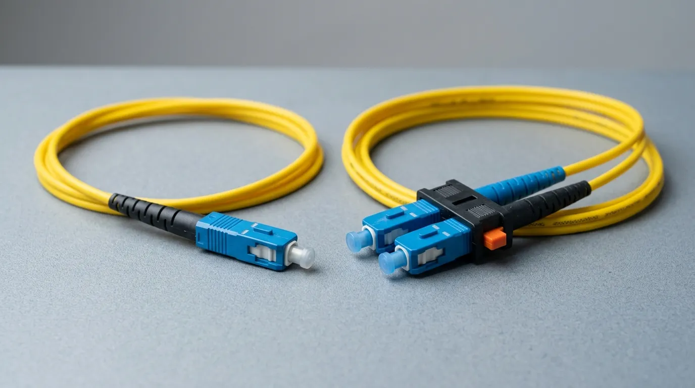
Count is a mechanical decision: a simplex cord carries one fiber and is used where one direction or one port is needed (an ONT drop, a test lead, a patch to a single transceiver channel). A duplex cord carries two fibers with a clip holding the pair, and it is what a bidirectional transceiver wants — one fiber for transmit, one for receive.
That clip is the source of the classic polarity error. A duplex pair can be wired A-to-A or A-to-B, and the two are not interchangeable: get it wrong and a whole row of links transmits into its neighbours' receivers. Key-up/key-down orientation and the clip's key are what make the pair land the way the port expects, so the two things to confirm before ordering a duplex cord are the polarity convention of your patching plan and the orientation of the clip.
Mode is a performance decision, and the two families do not interoperate:
Single-mode | Multimode | |
|---|---|---|
Grades | OS2 (with bend-insensitive variants to ITU-T G.657) | OM1, OM2 (legacy), OM3, OM4, OM5 |
Typical wavelengths | 1310 / 1550 nm | 850 / 1300 nm |
Reach & use | Metro, access, FTTH, long spans | Within a building or data hall; OM3/OM4 for 10G–100G, OM5 for short-wave multiplexing |
Jacket color convention | Yellow jacket; green connector bodies where the build is APC | Orange (OM1/OM2), aqua (OM3/OM4), lime green (OM5) |
Single-mode is the safer long-term purchase for anything that leaves the building, and bend-insensitive single-mode (ITU-T G.657) is worth specifying in tight enclosures, because it tolerates a much smaller bend radius without adding loss — the difference between a tidy patch and a raised-loss one is often routing, not the connector (ITU-T G.657). Multimode grade definitions and their distance ratings are set out in the structured-cabling conventions (optical fiber types) and compared grade by grade in OM1–OM5 grades. The mode decision itself — reach, transceiver cost, future migration — is treated in single-mode vs multimode.
Two consequences are easy to miss. A single-mode cord and a multimode cord can carry identical LC connectors and still be electrically incompatible: mode field diameter differs, so light launched across the mismatch is lost at the joint. And where an older multimode link has to be driven by a long-wavelength transmitter — the classic long-reach GBIC into OM1/OM2 — a mode conditioning patch cord offsets the launch point so the transmitter does not excite only the center of the core; it is a part number you buy deliberately, not a workaround you improvise with a standard cord.
Axis 4 — Cable Construction: Jacket, Armor and Environment
This is the axis that decides whether the cord is legal to install in the space you are running it through, and the one that gets value-engineered out.
Construction | What it is for | Where it is required |
|---|---|---|
PVC jacket | General indoor patching; cheapest | Cabinets and trays away from air-handling spaces |
LSZH (low-smoke zero-halogen) | Low smoke and no halogen acid gas if it burns | Enclosed spaces, tunnels, transit and where people evacuate; common in European specifications |
OFNR / riser | Vertical runs; flame spread limited for riser shafts | Between floors inside a building |
OFNP / plenum | Tested for low smoke in air-handling spaces | Ceiling voids used as return-air plenums — substituting a riser-rated cord here is a code violation, not a cost saving |
Armored | Corrugated steel or aluminium layer under the jacket | Rodent-prone routes, factory floors, direct burial and anywhere crush loads are real |
Tight-buffered / uniboot | 900 µm buffer directly on the fiber; uniboot puts two fibers in one jacket with one connector footprint | Dense racks; uniboot halves the cable mass in a duplex run and simplifies polarity changes |
Breakout / fan-out | One multi-fiber connector split into several simplex or duplex legs | MPO-to-LC transition in a data hall, where the trunk is MPO and the equipment is LC |
IP-rated / ODC / FTTA assembly | Sealed, often hybrid power-and-fiber, connectorised outside plant | Tower-top radio units and outdoor enclosures, where the connector must survive weather and repeated plugging |
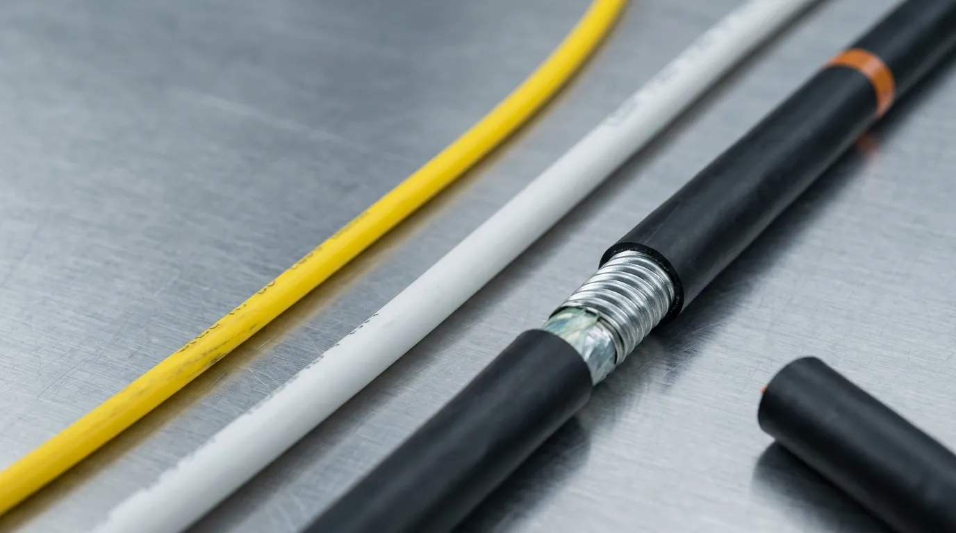
Inside the jacket, aramid yarn (Kevlar-type) strength members carry the tensile load so the fiber never does, and the assembly's rated tensile and retention figures are what tell you whether the cord can be pulled into a conduit or must be installed slack. The fire-rating axis has its own standards logic, covered in OFNP, OFNR and LSZH; the rule of thumb is to match the rating to the space, and to document it, because an inspector will ask.

Performance Numbers and the Standards Behind Them
A patch cord is bought on two measured numbers and a durability claim. Naming the standard behind each number is what turns a datasheet into a specification.
Parameter | Typical figure | What sets or defines it |
|---|---|---|
Insertion loss, per mated pair | ~0.3 dB max for a standard factory assembly; low-loss grades specified at ≤0.15 dB | Assembly datasheet; the generic connector range is 0.25–0.5 dB |
Mated connection loss limit, structured cabling | 0.75 dB max per connection | TIA-568 |
Return loss, mated pair | ≤ −50 dB (UPC, single-mode) · ≤ −60 dB (APC) · ≤ −30 dB (multimode UPC) | Datasheet, measured at 1310/1550 nm (SM) or 850/1300 nm (MM) |
End-face quality | Pass/fail on scratches, pits and contamination | IEC 61300-3-35 inspection criteria |
Interchangeability, mate/demate | ~500 cycles (1.25 mm ferrule) · ~1,000 cycles (2.5 mm) | Connector family rating — a real limit in patch-panel rows that get reconfigured |
Operating environment | e.g. −20 °C to +70 °C on a typical indoor assembly | Datasheet; match to the route, not to the room you are standing in |
Three practical points follow. First, "0.3 dB per connection" is a budget, not a measurement — the limit is what a standards-based link calculation is allowed to assume, and a good supplier's typical figure is well below it (FOA termination reference). Second, end-face condition is a first-order loss mechanism, not a cosmetic issue: contamination and scratches are the most common cause of a connection that measures badly, which is why the inspection criteria (IEC 61300-3-35) exist and why the measurement is done at the assembly, not at the port. Third, loss and reflection are measured at a wavelength, so a datasheet that quotes "≤0.3 dB" without a wavelength is quoting half a specification — the definitions side of this is in insertion loss and return loss.
How to Specify the Right Patch Cord in Four Steps
The four axes become one line item in four steps:
- Read the port, not the brochure. Interface and mating durability follow from the equipment and the patch panel you are plugging into — LC into SFP/QSFP cages, SC into most FTTH and patching fields, MPO where the trunk is multi-fiber.
- Match the polish to the signal. Digital Ethernet and FTTH patching: UPC against UPC, or APC against APC if the access network uses it (APC is the usual choice on FTTH). Analog video, RF-over-glass and reflection-sensitive links: APC throughout. Never mix the two ends.
- Choose count, mode and grade from the transceiver. Duplex for bidirectional optics, simplex for single-path, and OS2 or G.657 single-mode where the span leaves the building; OM3/OM4/OM5 where it stays inside and the optics are short-wave. Confirm the polarity convention for duplex pairs before the order goes out.
- Match the construction to the route. Plenum space → OFNP; riser shaft → OFNR; enclosed public space or a European specification → LSZH; rodent or crush exposure → armored; outdoor or tower-top → an IP-rated assembly. Record the length and the bend environment while you are there, and specify a length that leaves the routing loops you actually need.
The output of those four steps is a specification line, not a product name:
Spec field | Example value |
|---|---|
Interface | LC/UPC duplex |
Fiber & grade | OS2 single-mode, bend-insensitive |
Count & polarity | Duplex, A-to-B, clip key up |
Jacket / rating | LSZH, 2.0 mm round |
Length | 3 m |
Loss class | IL ≤ 0.15 dB typ / ≤ 0.3 dB max; RL ≥ 50 dB |
Test evidence | IL and RL measured at 1310 and 1550 nm, per assembly |
If you are replacing existing plant rather than building new, the fastest check against your own network is the guide to fiber optic cable types, which covers the cable side of the same decision.
What to Send a Supplier
The four axes tell a supplier what to build; a short list of questions tells you whether they can prove it was built that way. Ask for the following, in writing, in the RFQ:
- A test record for the assemblies you will actually receive — insertion loss and return loss, measured per assembly at the stated wavelengths, with pass/fail against the limits you specified. A range claim covering "up to 0.3 dB" is not the same thing as the data for your parts, and it is worth stating in the RFQ which wavelength is the reference for each figure.
- The loss and tolerance class in numbers, not adjectives. "Low loss" is not a specification; ≤0.15 dB typical with a maximum is.
- Retention and tensile figures, matched to how the cord will be installed, plus the bend-radius allowance for the jacket you chose.
- MOQ and lead time per configuration — this is where a customised assembly stops being a catalog item. Long assemblies, armored jackets, uniboot and MPO fan-outs all move the MOQ, and a supplier who answers this early is a supplier who has built the part before.
- Private label and OEM/ODM terms if the cord will carry your own part numbers, including labeling, packaging and the datasheet format you will resell.
- First-article samples before the bulk order, especially for duplex polarity, uniboot and any fan-out, because the failure modes in this category are all visible in the first piece.
On the testing side, the honest answer for most manufacturers is that assemblies are tested before shipment under a quality system rather than shipped with an interferometer report for every piece: at DYS, orders go through 100% testing before shipment under an ISO 9001 system with traceability records as standard, the lab includes a 3D interferometer for end faces, and reports are available on request — and the published figures for an indoor round patch cord assembly run to ≤0.15 dB typical / ≤0.3 dB maximum insertion loss with ≥50 dB (UPC, single-mode) or ≥60 dB (APC, single-mode) return loss over a 200-cycle durability rating. Treat any supplier's numbers the same way: ask which figure is typical, which is a maximum, and at which wavelength each was measured.
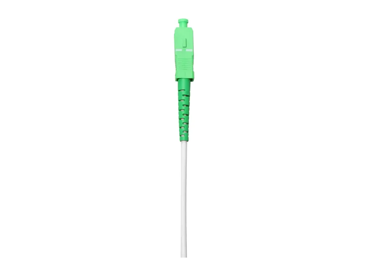
For the FTTH and access side of the catalog, the FTTH round patch cord covers the indoor/outdoor assembly in the specification format above.
FAQ
What are the four types of fiber optic connectors? The four fiber optic patch cord types you will meet in a general network are LC (1.25 mm ferrule, high density), SC (2.5 mm, square push-pull, the FTTH and patching standard), FC (2.5 mm, threaded, test gear and legacy telecom) and ST (2.5 mm, bayonet, legacy LAN). Add MPO/MTP if multi-fiber trunks are in scope, and MU, MTRJ, E2000, LX.5 and SMA only when matching existing plant.
Is LC better than SC for a patch cord? Not better — denser. LC halves the footprint and halves the ferrule diameter, which is why it dominates modern switch, OLT and router ports; SC is more tolerant of handling and is rated for more mating cycles. Pick the one your ports use, unless you are building the patching field from scratch.
Can I plug a UPC patch cord into an APC port? No — and the same applies in the other direction: never join a UPC end to an APC end. The angled end face and the flat one do not seat properly, which raises both insertion loss and reflectance, and repeatedly forcing them can damage the ferrule. Match polish to polish.
Single-mode or multimode patch cord — which do I need? Multimode (OM3/OM4/OM5) if the whole link stays inside one building or data hall and the optics are short-wave; single-mode (OS2) for anything that leaves the building, crosses a campus, or needs to be future-proof. They are not interchangeable, even with identical connectors, because the mode field diameter differs.
How do I tell what type of patch cord I am holding? Read it in this order: the connector body (LC, SC, FC, ST, MPO), the body color for the polish convention (blue for UPC, green for APC — but verify against the part number, since color is only a convention), the jacket color and print for the fiber grade and fire rating (yellow for single-mode, aqua for OM3/OM4, lime green for OM5, plus OFNR/OFNP where applicable), and the clip or key on a duplex pair for polarity. When the printed legend is ambiguous, a loss test at the specified wavelength settles the question.