
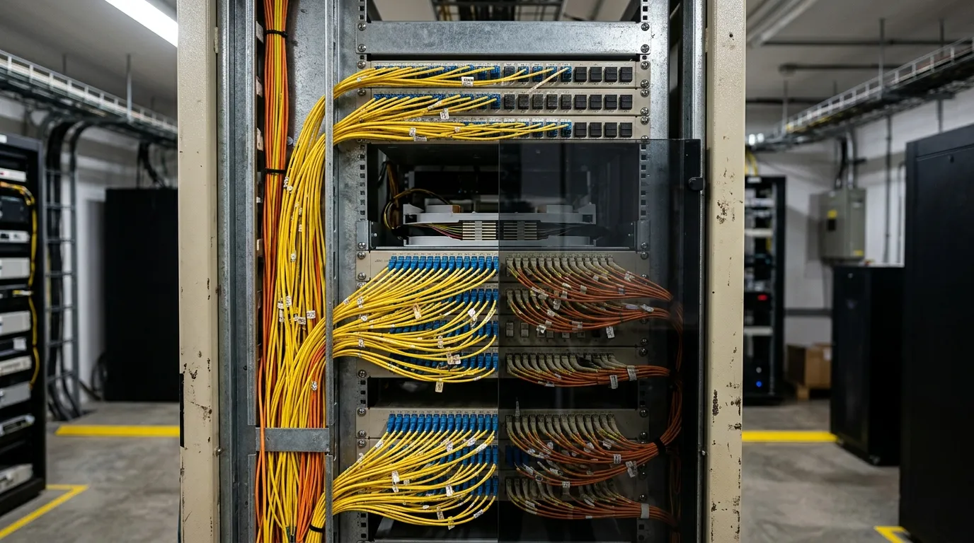
Fiber Basics
What Is an Optical Distribution Frame? ODF Guide
An optical distribution frame (ODF) is a passive frame that terminates incoming fiber cable, splices it to pigtails, and presents every fiber as a patchable port on the front — in one managed unit, with the slack and the labels to go with it. It is the point in a fiber network where a permanently installed cable becomes something a technician can rearrange. That is the short answer to "what is an optical distribution frame"; the long answer is the five numbers you specify before you buy, because the mounting styles, the port counts, and the price spread from a few hundred dollars to five figures all follow from them. Get those five right and the "which type of ODF" question mostly answers itself. Get them wrong and you own a very expensive steel box with the wrong adapters in it.
What is an optical distribution frame? Six jobs in one frame
An ODF does six jobs at one location:
- Terminates the incoming cable — the strength member and jacket are mechanically anchored to the frame, not to the fibers.
- Splices each fiber to a factory-terminated pigtail, usually by fusion splicing in trays.
- Patches those pigtails to the front adapter panel, so each fiber ends at a labeled port.
- Stores the slack from both the cable and the pigtails, at a radius the fiber tolerates.
- Protects the splices and connectors from dust, strain, and accidental contact.
- Administers the plant — port IDs, cable IDs, and frame IDs that make the next technician's job possible.
That combination is what separates an ODF from a box that merely holds connectors. A frame with adapters but no splice capacity, no cable anchoring, and no labeling is a patch panel; a frame with splices but no front ports is a closure. The ODF is the one component that does the whole transition in a single place.
In FTTH and metro networks this transition happens once, at the exchange or the street cabinet, and every later reconfiguration — a new subscriber, a moved ONT, a re-routed feeder — is done by moving a patch cord rather than by re-splicing cable. In a data center the same function appears as a high-density panel in the main distribution area, where trunks coming from the entrance room are broken out to LC or MPO ports. Same job, different packaging.
The five numbers that define an ODF
Vendors describe ODFs by mounting style first, which is backwards for anyone writing a purchase order. Mounting style is a consequence. These five numbers are the cause:
Spec | What it decides | Typical values |
|---|---|---|
Fiber count | How many ports you need now, plus growth | 12, 24, 48, 96, 144 |
Adapter interface | Which patch cords and pigtails fit | LC duplex, SC, MPO-8/12/24 |
Splice capacity | How many splices the trays hold | 12 or 24 per tray, 24–288 per frame |
Rack units / footprint | Vertical space or floor area consumed | 1U, 2U, 4U; or a 2.2 m floor frame |
Cable entry and anchoring | Whether your cable type physically lands | Top, bottom, rear; loose tube, ribbon, or indoor riser |
A 48-port ODF that holds only 24 splices is a trap: half your fibers can be patched but not spliced, so the "48-port" frame needs a second tray stack the datasheet did not mention. The same trap exists in reverse — 144 splice capacity with 24 adapters is a frame sized for a cable that is not there yet. Capacity in ports and capacity in splices are two different numbers, and both belong on the quote.
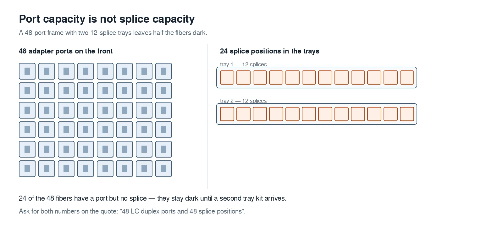
Two capacities, two line items. The quote should name both, or the frame arrives half usable.
Fiber count is usually decided by the cable, not by preference. Cables are built in 12-fiber units, so an ODF that ends a 96-fiber cable needs 96 ports and at least 96 splice positions — or 48, if the design splices only the fibers in service and leaves the rest dark. That decision has a cost either way, and it is cheaper to make it on paper.
Inside an ODF: what the money actually buys
A rack-mount ODF is a sheet-metal frame with four functional zones. Knowing them is how you read a datasheet, and how you spot the models that saved money in the wrong place.
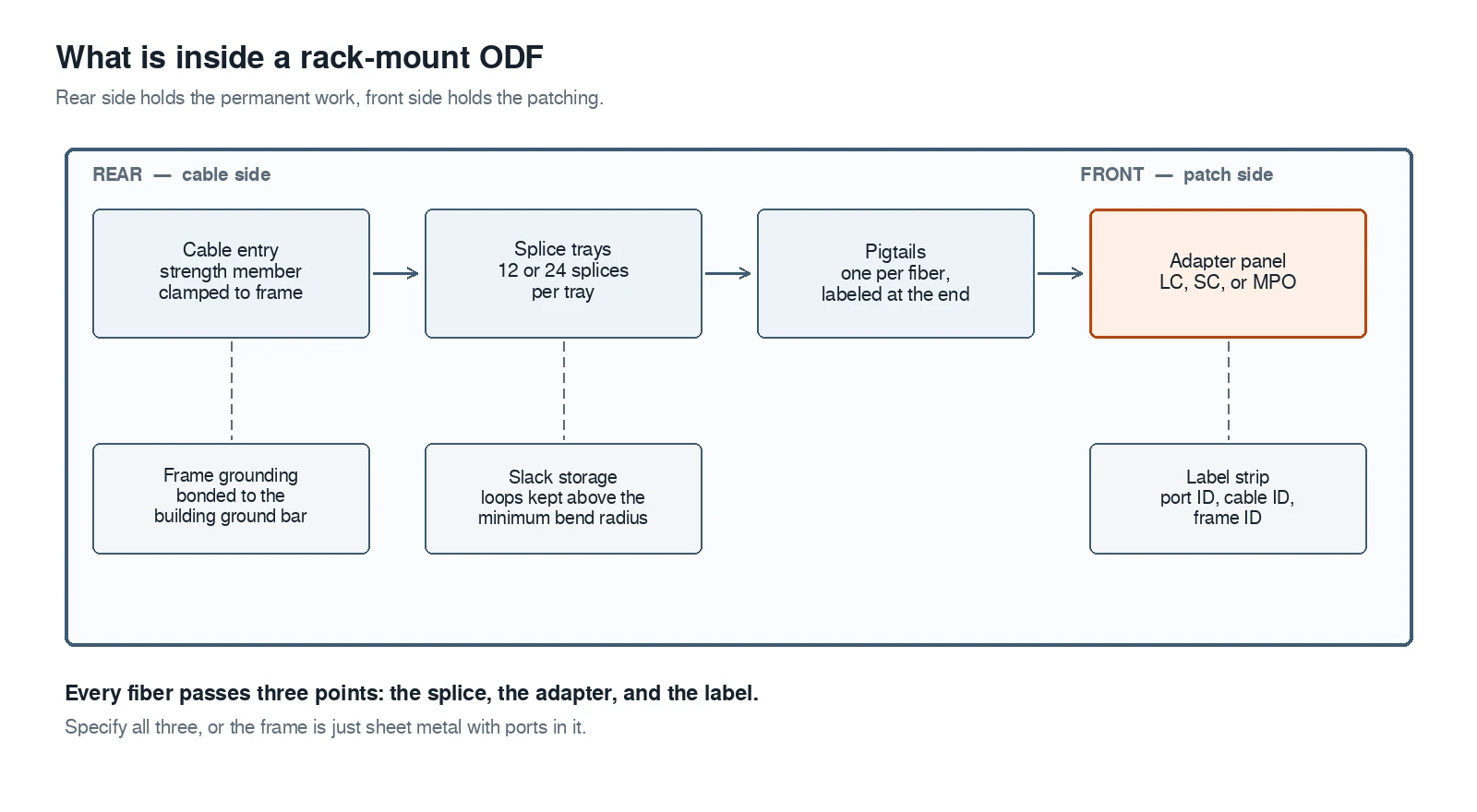
Rear side holds the permanent work — cable anchoring and splices. Front side holds everything a technician is allowed to touch.
Cable entry and anchoring. The cable enters through a gland or a grommet plate, and its strength members are clamped to the frame. This is the detail that separates an outdoor-rated frame from a shelf: a loose-tube cable with aramid yarn needs a clamp that grips the yarn, not the tubes. If the datasheet does not say how the cable is anchored, assume it is not.
Splice trays. Each tray holds 12 or 24 fusion splices and protects them with a cover. Trays are stacked and hinged, so a technician can open the second tray without disturbing the first. Tray count sets splice capacity, and tray depth sets the bend radius the slack must respect.
Pigtails and the adapter panel. A pigtail is a short factory-terminated fiber; one end is spliced to the incoming fiber, the other plugs into the back of an adapter. The adapter panel on the front is the interface that matters to everyone downstream: LC duplex for switch and OLT ports, SC where single-fiber legacy links exist, MPO where parallel optics or trunk breakouts are involved. Interface dimensions for LC are fixed by IEC 61754-20 — which is why an LC adapter from one vendor accepts an LC connector from another, and why "LC-compatible" is not a real specification. Our guide to fiber optic adapters and couplers covers the flange and sleeve variants if you are mixing brands in one frame.
Slack storage and grounding. Slack loops are stored on the frame at a radius the fiber tolerates — tight coiling is the most common cause of loss that appears months after installation. On frames that accept cable with metallic strength members, the strength member and armor bond to the frame, and the frame bonds to the building ground bar. That bonding detail is usually a line item in a telecom-room specification and frequently missing from the cheap models.
Pigtails are the component most often bought separately from the frame, and the grade matters: a frame full of cheap pigtails will test badly no matter how good the frame is. Jacket type, fiber grade, and polish are specified separately from the frame itself — our guide to fiber pigtails covers the options — and the reason to care is in the next section. Before any of them go into a tray, the jacket print and the fiber colors tell you which fiber is which: the 12-position color sequence is published as a fiber color code reference, and reading it correctly is what stops a splice from landing on the wrong fiber.
Types of ODF: four families and where each belongs
The three classic types are still the right starting point, with a fourth that has taken over data centers.
Family | Capacity | Where it belongs | What to watch |
|---|---|---|---|
Wall mount ODF | 12–48 fibers | Small POPs, building entrance rooms, remote sites | Door swing and cable bend radius in tight corners; limited splice depth |
Floor-standing ODF | 96–576 fibers | Central offices, exchange buildings, large campuses | Footprint and front clearance; open frames need a secured room |
Rack mount ODF | 24–144 fibers in 1U–4U | Data centers, equipment rooms, huts with 19" racks | Rack-unit budget; rear cable access; whether trays pull out |
High-density / modular ODF | 144–720 fibers per rack | MDAs and IDAs in data centers, MPO-heavy plants | Cassette cost per port; polarity discipline; cleaning access |
A wall mount ODF is a small enclosure, usually with a hinged door, sized to end a cable that serves one building. It is the right answer for 24 fibers in a basement room and the wrong answer for a 144-fiber feeder, mostly because the splice trays and the cable bend radius will not fit in the same box.
A floor-standing ODF is the traditional exchange frame: a steel structure with vertical cable guides and rows of adapter panels, open at the front so a technician can work at any height. Open frames are cheap per port and easy to expand; they also require a room that only authorized people enter, because there is nothing between a passer-by and a live connector.
A rack mount ODF is the data-center and hut form: a 19-inch panel 1U to 4U high, sliding or fixed, with adapters on the front and splice trays or cable management behind. One rack unit is 44.45 mm, so a 4U frame gives you roughly 178 mm of working height — enough for four rows of LC duplex adapters or two rows plus a tray stack, and the arithmetic decides how many ports fit before you look at any drawing.
High-density frames replaced adapter plates with cassettes: an MPO connector on the back fans out to 12 or 24 LC ports on the front, so a 1U panel can present 96 or 144 ports. The trade is that a cassette is a fixed module — changing from LC to MPO means changing cassettes, not just adapters — and the polarity rules that apply to MPO trunks apply inside the frame as well.
Where the ODF sits in the network
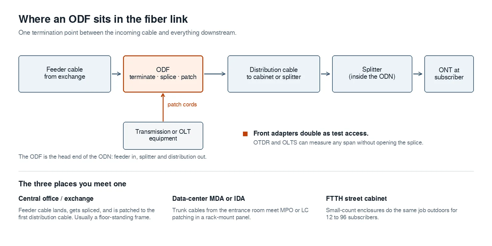
The ODF is a boundary, not a node: everything left of it is permanent plant, everything right of it is patching. It is also where the ODN starts — the feeder lands here, and the first splitter sits downstream of the frame.
Read the chain from left to right and the design rules fall out. The feeder cable is spliced once and never touched again; the transmission equipment is patched in and out as it is upgraded; the distribution side is where subscriber churn happens. Every one of those transitions passes through the same frame, which is why ODF port counts are usually sized for the distribution side rather than the feeder.
In a PON network the ODF sits at the head end of the ODN — between the OLT's optical port and the first splitter, not after it. The OLT, ONU, ONT, and ODN roles are worth keeping straight here, because a frame sized as if it were a splitter cabinet will run out of ports as soon as the split ratio changes.
The frame is also the test point. Front adapters let an OTDR or a light source and power meter reach any span without opening a splice tray: unplug the patch cord, connect the instrument, measure, reconnect. That is the operational reason the front panel exists at all, and it is the reason a frame with glued-in pigtails and no accessible adapters is a false economy.
What an ODF is not: patch panel, terminal box, distribution box
Most of the confusion around ODFs comes from three neighboring products that look similar in a catalog photo.
ODF vs patch panel. A patch panel terminates cable and presents ports; it does not normally hold splices, and it expects a pre-terminated cable or a pigtail spliced elsewhere. A fiber patch panel is a rack unit for cross-connecting; an ODF is a frame for landing cable. In a data center the two functions are often combined in one 1U panel, which is precisely why the terms get mixed. Our fiber patch panel guide covers the panel side in detail.
ODF vs terminal box. A terminal box is the small-count version of the same idea, sealed for outdoor use, typically 4 to 16 ports, with no room for a large splice tray stack and no expectation of frequent patching. In an FTTH network the terminal box is where the drop cable is connected; the ODF is where the feeder is.
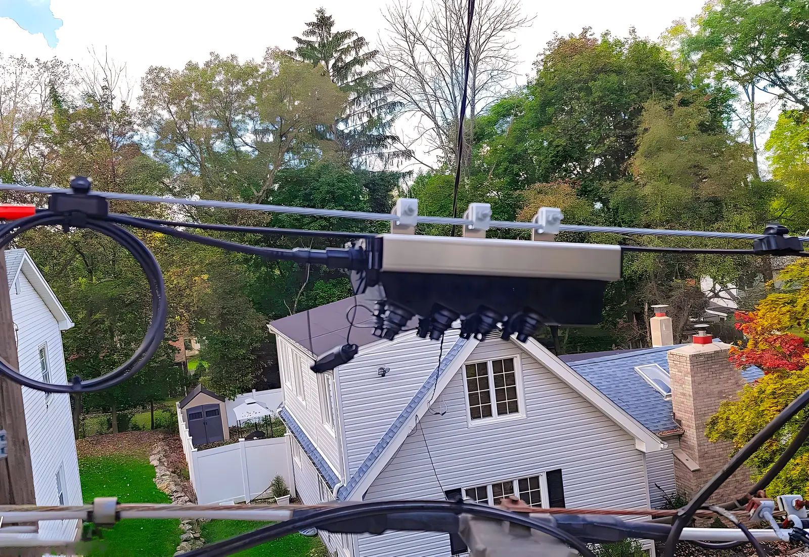
An outdoor drop enclosure doing the small-count end of the job. Same principle, different scale and no patch field.
ODF vs distribution box and closure. A distribution box organizes and protects splices or splitter outputs; a splice closure protects splices in the ground or on a pole. Neither is built for routine patching, and neither is administered like a frame.
The boundary in one sentence: if a technician is expected to move connections by hand, it is an ODF or a patch panel; if the connection is meant to be made once, it is a box or a closure. The naming conventions of the three small-count products differ by market, and our comparison of the terminal box, distribution box, and junction box untangles them.
How to specify an ODF you can actually deploy
An ODF purchase order that produces the right frame on the first attempt reads like this:
- Port count and interface. "48 LC duplex ports, UPC" is a specification; "48-port ODF" is not — it could mean 48 LC, 48 SC, or 24 duplex positions.
- Splice capacity, separately. State the number of splices, the tray capacity you will accept, and whether trays must be hinged and individually removable.
- Mounting and dimensions. For rack mount, the rack units and whether the frame must slide out for rear access. For floor-standing, height, width, and depth with the door open.
- Cable entry. Cable type, diameter range, entry direction, and how the strength member is anchored. For outdoor cable add the gland type and whether the frame is rated for it.
- Adapter and polish discipline. Do not mix APC and UPC in one frame unless the design says so deliberately: an APC connector mated to a UPC adapter raises excess loss and collapses return loss from the >50 dB a UPC link is specified for down to the teens — the reflection, not the loss, is what breaks the link. The 8° difference sits on the ferrule endface, so do not rely on housing colour to sort mixed-vendor stock.
- Administration. Port numbering scheme, label type, and whether the frame arrives pre-labeled. The ANSI/TIA-606 administration standard is the reference most telecom rooms are built to; a frame with no label plan becomes unadministered within a year.
- Acceptance test. Endface inspection to IEC 61300-3-35 and a loss measurement per port, recorded against the port ID. If the vendor's acceptance sheet does not name a test, you are the test.
Two of those seven are routinely left off purchase orders and cause most of the rework: the separate splice capacity, and the cable entry. Everything else can be fixed in the field; those two cannot.
Five ways ODF projects go wrong
Port count bought, splice capacity assumed. The frame arrives with 48 adapters and two 12-splice trays. Twenty-four fibers stay dark until a second tray kit ships.
Slack tied tighter than the bend radius. Coiled pigtails at a 10 mm radius look tidy and test fine at commissioning. Loss creeps in over months as the fiber relaxes and the coating strains.
Polish mismatch at the boundary. An APC pigtail into a UPC adapter is a guaranteed high-reflection port: return loss drops from the >50 dB a UPC link is built for to the teens, and no loss budget on paper catches it. It also survives a visual check of the connector body, because an 8° polish lives on the ferrule endface and APC housings are only conventionally green — mixed-vendor parts can look alike and still be wrong.
Cable anchoring skipped. The strength member is left unclamped because the gland did not fit. Every future cable movement now loads the splices directly.
No label plan. Ports get numbered in installation order. Two years later nobody can map port 37 to a subscriber without a tone test, and the frame's main operational advantage — reconfiguration without re-splicing — is gone.
None of these is an ODF quality problem in the narrow sense. They are specification problems, which is why the five numbers matter more than the brand on the door.
Where to go next
If you are landing a feeder cable, size the frame from the distribution side and specify splice capacity separately from ports. If you are building out the small-count end of an FTTH network, the sealed enclosures are a different product family — our outdoor terminal boxes cover that range, and the Fiber Optics 101 hub has the cable and connector basics that feed into it.
For the parts that go inside the frame, the two decisions that matter most are pigtail grade and adapter interface. Both are cheap to get right at the order stage and expensive to correct after the cable is spliced.