
Fiber Basics
How Do Fiber Optic Cables Work? Total Internal Reflection Explained in Plain English
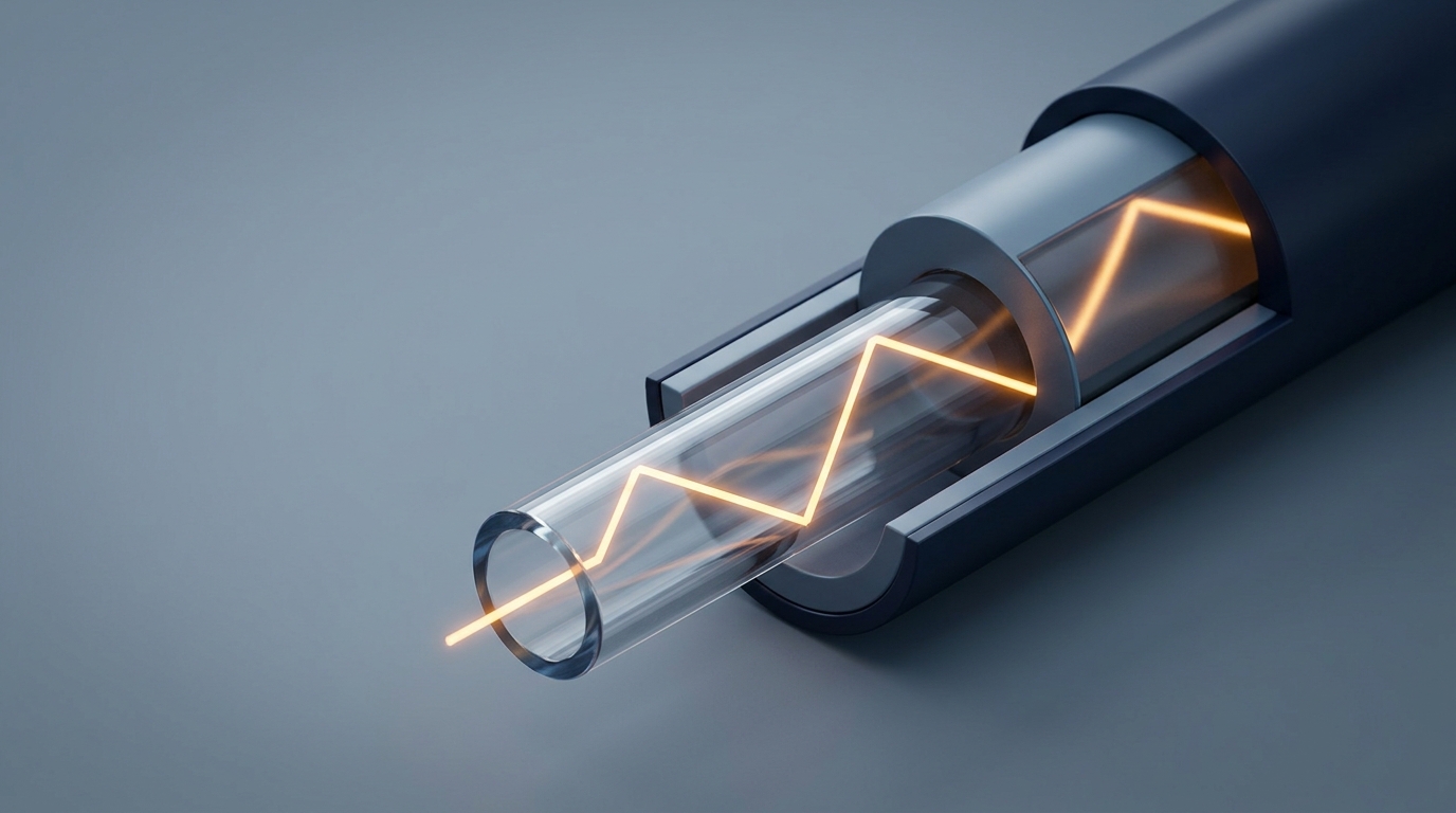
How do fiber optic cables work? Light launched into a glass core strikes the boundary with the surrounding cladding at too shallow an angle to pass through, and is reflected back into the core. The cladding does the reflecting. There is no mirror coating inside a fiber, which is why one strand of glass can carry light for kilometers.
That is the entire trick, and it fits in two sentences. It is also where most answers to how does fiber optic cable work stop — and the stopping point costs money, because the physics explains why light gets in, not why your link works. A fiber that guides light perfectly still fails if the cable around it is wrong, if the end face is dirty, or if somebody pulled it around a corner at the end of a conduit run.
So this page does two things: the mechanism at the depth you need to judge a spec, then the part that decides whether the glass gets to do its job. Our Fiber Optics 101 guide is the index to this series if you want the map before the detail.
What is actually inside a fiber optic cable
The first correction is terminological, and once you separate the two things people both call "fiber," the rest of how fiber optic cables work gets much easier.
The fiber is the glass: core, cladding, and a thin protective coating. Everything about how light moves is decided in those three layers, in a cross-section about a quarter of a millimeter across.
The cable is the machine wrapped around it so the fiber can survive being installed. Parts of a fiber optic cable add buffer layers, tubes, strength members, water blocking and a jacket. None of them guide light. All of them decide whether the light is still arriving in ten years — the half of the fiber optic cable how it works question that physics cannot answer.
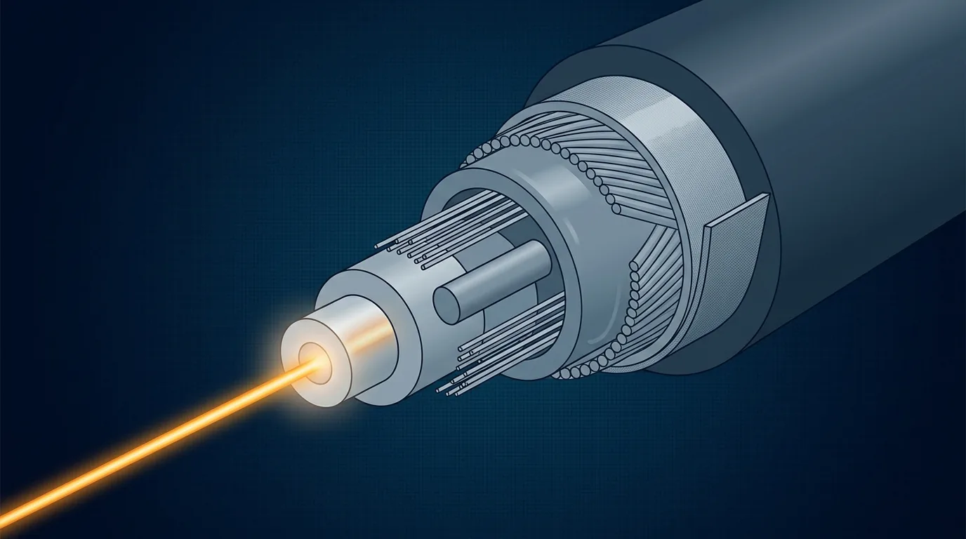
The glass guides the light. Everything outside it exists to keep the glass intact.
The glass part: core, cladding and the index step
Telecom fiber is drawn from ultra-pure silica. Contamination is measured in parts per billion, because a stray hydroxyl group or metal ion absorbs light and cannot be fixed downstream. The core is doped — usually with germanium — to raise its refractive index a fraction above the cladding's. A fraction is the honest word: the difference is a bit under one percent (1.46 against 1.45), and it is the whole fiber optic cable refractive index difference. That is also why cladding is not packaging — it is an optical element with a refractive index as carefully controlled as the core's.
Dimensions follow from it. Single-mode fiber shrinks the core so far down that one path survives: the Fiber Optic Association's fiber reference gives single-mode as 8–10 microns, specified as "mode field diameter," inside a 125 micron cladding. Multimode keeps a wider core — almost always 50 or 62.5 microns — and supports many paths at once. Both are 125 microns outside, close to the thickness of a human hair, which is the number that makes connectors and splices interchangeable worldwide — and it is why the fiber optic cable core diameter, not the cable's, is what an installer has to match.
The mechanical part: what the other few millimeters do
Above the bare glass sits a stack of layers, each solving one failure mode. This is the fiber optic cable structure from the glass outward, and the first layer goes on during drawing: a 250 micron acrylate coating that seals the pristine surface, because the glass is never more vulnerable than in the seconds between leaving the furnace and being coated.
Layer | What it is for | What fails without it |
|---|---|---|
Acrylate coating (250 µm) | Seals the glass surface from moisture | Surface flaws grow; fiber breaks at low load |
Tight buffer (900 µm) | Supports one fiber so a person can handle and terminate it | Fiber must stay inside a tube forever |
Loose tube, gel or dry water-blocking | Lets fibers float free of the cable's strain and thermal movement | Micro-bending as the cable contracts and stretches |
Aramid yarn and strength member | Carries tensile load so the glass never does | Pulling tension lands on glass; hidden micro-cracks |
Water-blocking tape, armor | Stops water migrating along the cable; resists rodents | Water reaches the core; hydrogen darkening raises loss for years |
Outer jacket (PE outdoor, LSZH indoor) | UV, abrasion, chemical and fire-rating protection | Everything above, plus the fire class a tender specifies |
The distinction that matters most is whether fibers sit loose or tight. Loose-tube construction is the outdoor default: fibers float in a gel-filled or dry tube, isolated from everything the cable does. Tight-buffered construction wraps each fiber individually for patch cords and indoor risers, where a person will handle it. Neither is better, and picking the wrong one for the route is a common, avoidable mistake. Seeing how those fiber optic cable components are assembled on a real line is a factory question — how the cable is actually built walks it from preform to jacketed reel.
How do fiber optic cables work? Total internal reflection and the critical angle
Light crossing from a denser medium into a less dense one bends away from the boundary — Snell's law, and the reason a stick looks broken in water. What matters here is what happens as the angle gets shallower. There comes a point where the refracted ray lies flat along the boundary instead of emerging, and past that point no light escapes at all. It reflects at full strength, as if the boundary were a mirror.
That point is the critical angle, and it is set entirely by the ratio of the two indices. Using the FOA's worked values — core 1.46, cladding 1.45 — the critical angle comes out near 83.2 degrees measured from a perpendicular to the boundary — equivalently, 6.8 degrees off the fiber's axis. Rays arriving within that cone bounce along the core for kilometers; rays arriving at an angle beyond it cross into the cladding and are gone. Throughout this section, angles are quoted from the perpendicular unless the text says otherwise.
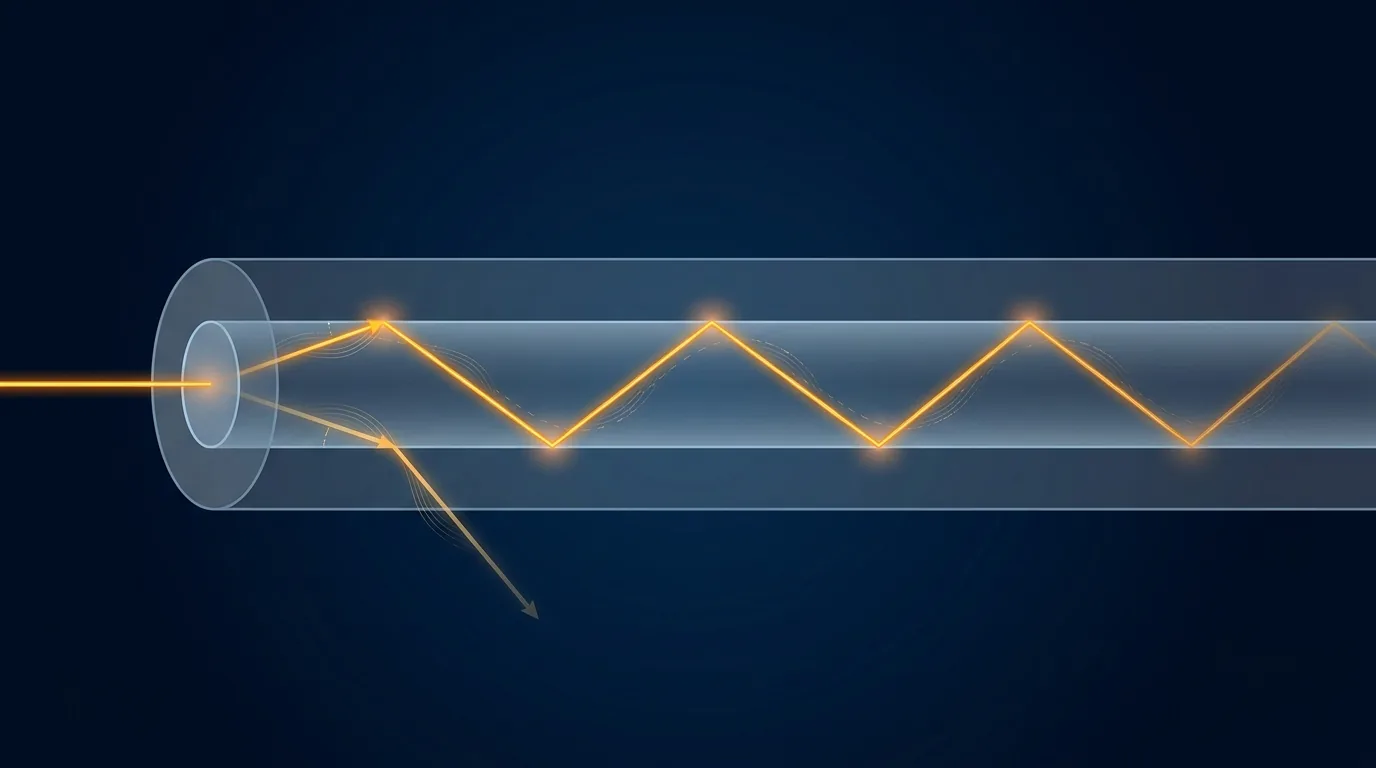
Same glass, same boundary, two outcomes — the only variable is the angle of arrival.
Three details in that fiber optic cable diagram are worth carrying into a specification conversation.
Light does not travel straight down the middle. It zig-zags, reflecting a few thousand times per meter at a shallow launch angle — the spacing between bounces follows directly from the core diameter and the angle — so the optical path is longer than the cable. Silica's index of about 1.46 puts light in a fiber at roughly two-thirds of the speed of light in a vacuum.
The reflection needs no coating, and that is not a curiosity — it is why fiber is practical. A mirrored tube kilometers long would be impossible to make, and a metallic coating would absorb light at every bounce. A refractive-index boundary reflects without absorbing.
And a leak is built into the design. Where the boundary does not reflect — at a tight bend — light crosses into the cladding, and in a normal fiber it is gone. Manufacturers fight that with a designed index profile, and the standard that constrains the result is one we come back to below.
Numerical aperture and the acceptance cone
The critical angle also sets how much light gets into a fiber. The numerical aperture of optical fiber is the sine of the half-angle of the cone it will accept. For the same 1.46/1.45 fiber the FOA calculates a half-angle near 9.8 degrees, a total acceptance cone of about 20 degrees.
The FOA is direct about what the number means: "The numerical aperture of an optical fiber is an abstract term for the acceptance angle of the fiber."
That is not trivia. It explains why launching light takes micron alignment while a camera lens can simply be pointed, and why multimode — wider core, correspondingly wider numerical aperture — is far more forgiving to terminate. It also explains an expensive mistake the FOA warns about bluntly: joining single-mode to multimode can cost around 20 dB, which is 99% of your power, and even a 62.5/125 to 50/125 mismatch loses 3 dB or more. Modes that do not fit the receiving core have nowhere to go.
One path or many: what single-mode and multimode change
The two fiber families are not competing products. They are answers to the same problem, and the answer falls out of distance.
Shrink the core until one mode fits and you get single-mode: one path, no path-length differences to reconcile, and the lowest attenuation available — the fiber family standardized as ITU-T G.652. Widen it and you get multimode, which accepts many modes — every one traveling a slightly different distance. Modes on longer paths arrive later, smearing each pulse. That is modal dispersion, and it is why a wide core cannot simply be scaled up in distance.
Graded-index multimode is the fix: the core's composition is varied so outer modes travel through lower-index glass and speed up, arriving together. It works well enough to keep multimode dominant indoors, where 850 nm optics are cheap and runs stay short. On attenuation, the FOA's typical figures for laser-optimized 50/125 multimode (OM3–OM5) are about 2.5 dB/km at 850 nm, against about 3 dB/km for the older OM1 and OM2 grades, and roughly 0.25 dB/km at 1550 nm for single-mode — a roughly tenfold gap between 850 nm multimode and 1550 nm single-mode that decides which fiber belongs on a 20 kilometer route.
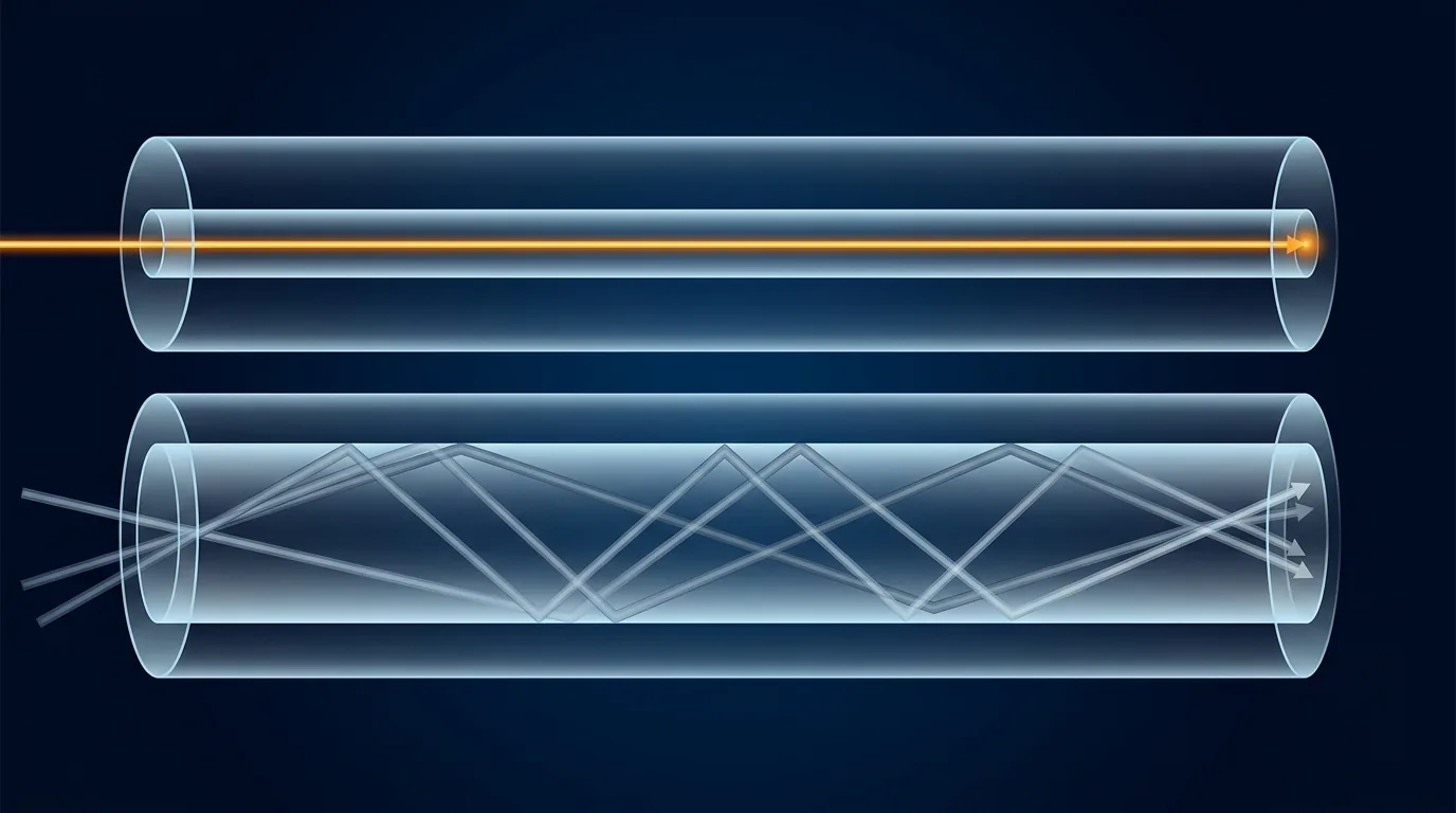
One mode means no path-length differences to reconcile; many modes cost bandwidth and cap the distance.
So "which is better" is the wrong question, and the practical version — reach, optics cost, upgrade headroom — is worked through in our single-mode vs multimode comparison. What matters for the mechanism is that both families obey the same rule and are limited by the same loss.
How do fiber optic cables transmit data?
Guiding light is not the same as sending information, and the question of how do fiber optics transmit data is where most mental models are thinnest.
At one end a transmitter converts an electrical signal into light: LEDs or vertical-cavity lasers for short multimode links, laser diodes at precise wavelengths for telecom. The light is switched on and off, or modulated in phase and amplitude, to represent bits — so the beam arriving at the far end is not a steady glow but a stream of discrete pulses. A photodiode reverses the conversion.
The part people miss is how much capacity comes from wavelength rather than switching speed. A fiber window is transparent across a wide band, so many wavelengths share one strand at once, each carrying its own signal. The channel plan is a standard, not a convention: ITU-T G.694.1 fixes the dense wavelength-division multiplexing grid, which is what turns one fiber pair into dozens of logical links. The FOA notes a single-mode fiber's theoretical bandwidth is on the order of 100 terahertz — limited in practice by the electronics at either end, not by the glass.
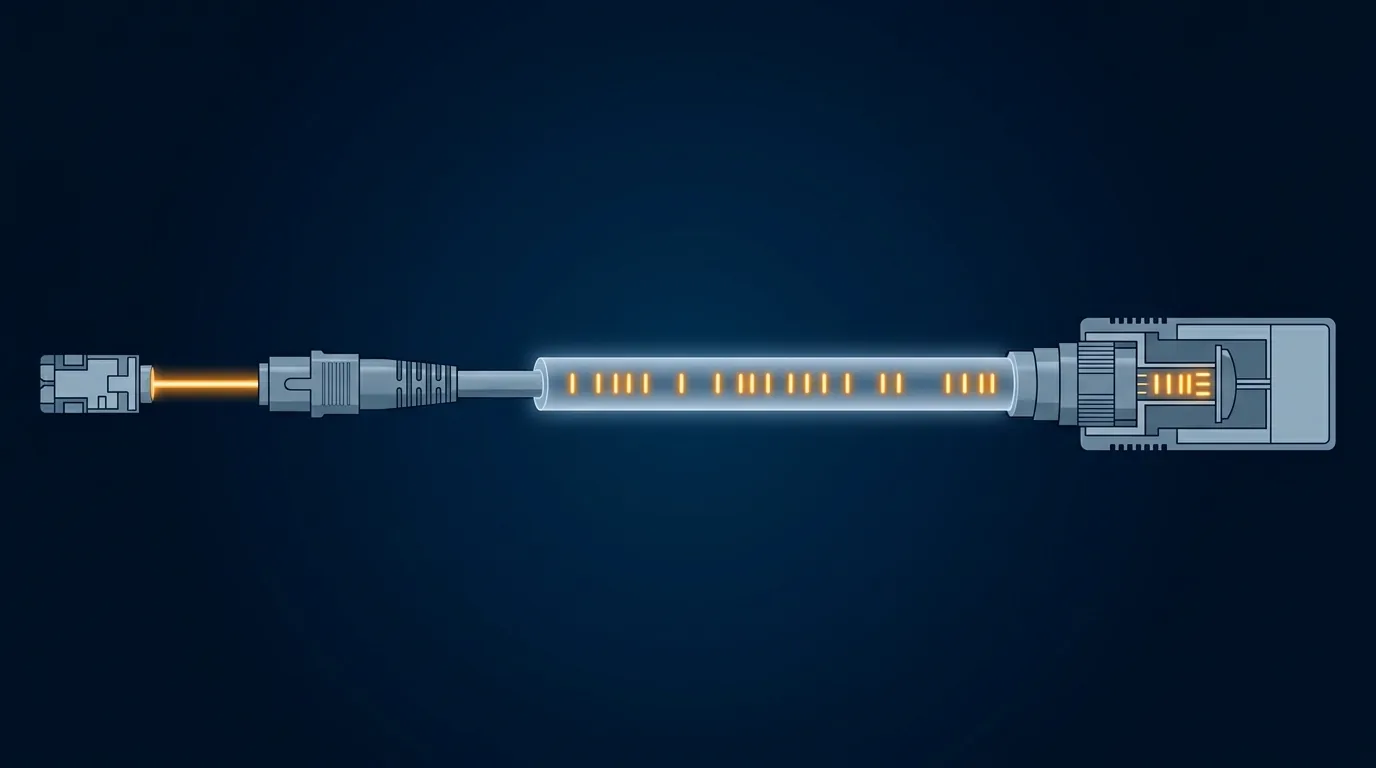
The fiber carries pulses. Everything expensive — and everything that limits reach — sits in the boxes at either end.
Two consequences follow, and they explain why fiber replaced copper for distance rather than everywhere. Light in glass ignores the electromagnetic interference that plagues copper pairs, and strands in one cable cannot crosstalk, because the light never leaves the core. Reach is limited by loss, not by noise, which is the trade our glass and copper comparison sets out. And long spans still need regeneration — but every regeneration point is powered electronics, not a passive repeater. Cheap glass plus costly terminals is the economics of the whole industry, and it is decided by the loss figure we get to next.
Not every link carries data, either. The same light path is what carries the image in a medical endoscope, and a single fiber doubles as a sensor whenever the strain or temperature along it changes how much light comes back — the basis of distributed fiber sensing.
Why the signal still dims: attenuation, wavelength and bends
Here the fiber optic cable working principle turns into an engineering problem. A perfectly reflecting boundary still loses light, for two reasons that have nothing to do with the boundary.
Absorption. Molecules convert a small fraction of the light into heat, at wavelengths set by which elements are present. The dominant absorber has historically been residual hydroxyl (OH) from water, with bands near 1000 nm, 1400 nm and beyond 1600 nm. Low-water-peak fiber suppresses most of that, which is what opened the band around 1383 nm to traffic.
Scattering. In a good fiber this is the bigger effect: Rayleigh scattering, light colliding with the atoms of the glass and being redirected, with loss proportional to the inverse fourth power of wavelength. Double the wavelength and scattering falls sixteenfold. That single relationship explains the shape of the attenuation curve and why long-haul systems run in the infrared.
The FOA's reference states the mechanism plainly: the attenuation of optical fiber "is a result of two factors, absorption and scattering," with scattering "proportional to the inverse fourth power of the wavelength of the light."
Three windows and one water peak
Put absorption and scattering on one axis and you get the loss curve every fiber engineer eventually memorizes: high at short wavelengths, falling steeply, spiking where absorption bands sit. Traffic lives in the clear gaps between them.
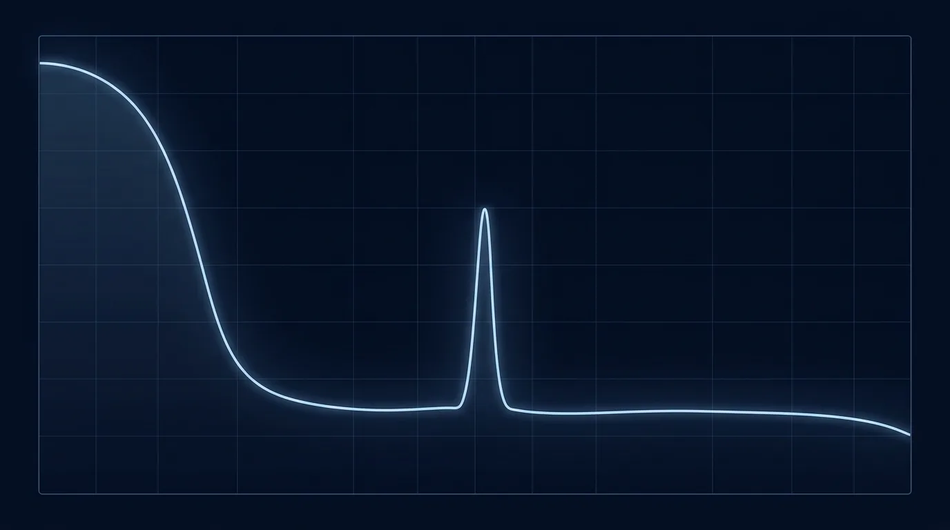
The gaps between absorption bands are the windows. Longer wavelengths are quieter because scattering falls off as the fourth power of wavelength.
Window | Typical use | Why there |
|---|---|---|
850 nm | Multimode indoors | Cheapest VCSEL optics; loss does not matter over short runs |
1310 nm | Single-mode access and metro | Low loss, near-zero dispersion in standard single-mode |
1550 nm | Long haul, PON, backbone | Lowest attenuation — the FOA's typical figures put single-mode near 0.2–0.3 dB/km |
1383 nm | Low-water-peak fiber only | The OH absorption spike, suppressed in modern fiber |
Those numbers convert straight into a distance limit. At roughly 0.25 dB/km, twenty kilometers of good single-mode cable costs about 5 dB before you count a single splice, connector or margin. In the 850 nm multimode window, where the older OM1 and OM2 grades run at about 3 dB/km, the same twenty kilometers would cost 60 dB — a factor of a million in power, and unbuildable. It is also why "how far can a fiber cable go" has no universal answer: distance is a property of wavelength, cable and joint count, not of glass alone.
One clarification, because the inverse mistake is common: this is the mechanism, not a budget. The FOA's reference on fiber loss covers how the coefficient is actually measured, and pass/fail thresholds belong with the subject of insertion and return loss, where the acceptance numbers live.
Bends, and why G.657 exists
Bend loss comes in two flavors, and conflating them produces bad specifications.
Microbending is leakage at microscopic scale — fiber pressed against a rough surface, pinched by a coating or by a construction that changes dimension in cold. It accumulates invisibly across a reel and shows up as a slightly worse attenuation coefficient than the fiber datasheet promised.
Macrobending is the one you can see: a bend tight enough that some rays strike the boundary at an angle beyond the critical angle and cross into the cladding. It gets worse at longer wavelengths, the opposite of the scattering trend — which is why 1625 nm is the wavelength used to test for bend faults.
Bend-insensitive fiber is not made by widening the core–cladding index step. Manufacturers add a low-index trench of glass around the core that guides escaping light back in, which is what ITU-T G.657 codifies and why patch cords and anything routed inside tight enclosures are usually bend-insensitive today. The cable's mechanical bend radius is a separate spec set by construction — our cable types by application covers which constructions carry which of those numbers into a tender.
Where the light is actually lost: end faces, splices and bends
Everything above is glass. Here is the uncomfortable part: on most real links, the glass is not what fails.
A cable run is not one fiber. It is many sections joined end to end, terminated at both ends, stored in loops. Each of those events lets light out, and the loss at those points dwarfs the attenuation of the cable they interrupt.
Fusion splices are the cheapest loss point you will ever make — two fibers welded with an electric arc and a good cleave. Mechanical splices and connectors cost more and vary more, because they depend on a ferrule, a spring, a polished end face and a human. And the largest single cause of connector trouble in the field is contamination. A fingerprint or a speck of dust on a 9 micron core end face blocks light and, at high power density, can burn the surface permanently. On more installations than anyone likes to admit, the link that fails acceptance testing is fixed with a cleaning tool.
Installation practice decides whether joints stay good. Pulling cable past its tension rating embrittles glass without visible damage, and the failure appears months later as rising loss. Water entering a cable raises attenuation slowly through hydrogen effects. Temperature cycling works the cable's structure against its own strength members, and that is exactly why the environmental test sequence — not the fiber datasheet — catches a design error in the cable.
This is the part a manufacturer sees from the inside. Every reel we ship is tested before dispatch as part of the ISO 9001 and ISO 14001 governed quality system, not sampled; the mechanical and environmental sequence behind that sign-off runs on an in-house reliability lab covering tensile, bend and torsion loading, temperature and humidity cycling, salt spray and IPX8 immersion, with connector test methods conforming to GR-326. The reason to care is the one stated above: a reel that ships without test data traceable to its batch leaves the physics with nothing to work with — traceability records are standard on our reels, and the test reports are available on request.
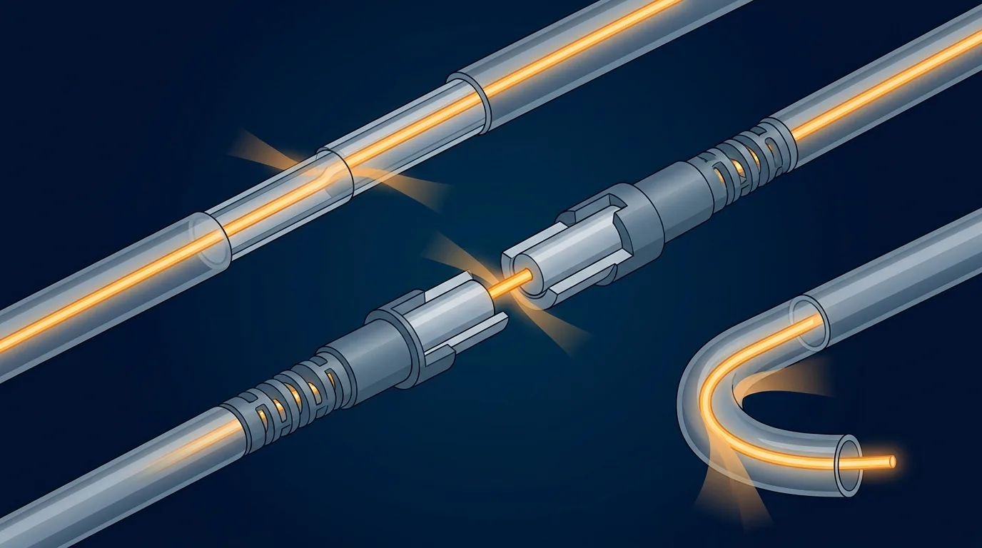
Three loss points, one cable: the welded joint, the mating connector, and the bend that exceeds the radius spec.
Two mechanical rules cover most of the damage, and the FOA's bend radius reference is blunt about both. The rule of thumb is 20 times the cable diameter under pulling tension and 10 times once installed — but plenty of cable carries different figures, sometimes 15 instead of 20, so the datasheet beats the rule every time. And the unit trap is real: if the requirement is a radius and the hardware is a pulley, the pulley needs 40 times the cable diameter, because a diameter is twice a radius. Storage loops, manholes and service loops are where that arithmetic quietly breaks.
Testing is the other half. An OTDR characterizes a whole span from one end, showing each splice and connector event against distance; a light source and power meter give the end-to-end number acceptance tests are written on. Our field testing walkthrough covers both instruments and when each is the right answer.
What the mechanism tells you to specify
Every constraint above becomes a line on a specification, and that is the payoff for reading the mechanism rather than the marketing.
Physical constraint | What it becomes on a spec sheet | What to ask a supplier |
|---|---|---|
Light is trapped only within the acceptance cone | Minimum bend radius, loaded and unloaded, with cable diameter quoted | Which multiplier applies to this construction — 20D or 15D under tension? |
Bend loss worsens at longer wavelengths | Bend-insensitive fiber grade where routing is tight | Is the drop or patch fiber G.657, and which sub-category? |
Short wavelengths scatter far more | Mode and wavelength choice, then reach | What is the attenuation coefficient at the wavelength you intend to run? |
Every joint costs more than the cable it interrupts | Splice count, connector grade, end-face inspection routine | What are the connector and splice loss figures this assembly is tested to? |
Water and hydrogen raise loss over years | Jacket and water-blocking construction, armor where relevant | Which water-blocking method, and what jacket compound and fire class? |
Temperature cycling stresses the cable | Operating temperature range, plus test evidence | Which environmental tests does each reel get, and can I see a record? |
The three contexts our readers build map cleanly onto those rows: FTTH drop cable, where a tight service loop around a building corner is the risk; high-density data center cabling, where joint count rather than cable length dominates the loss; and tower-top wireless fronthaul, where temperature swing, water ingress and a tight bend radius arrive together. Same physics in all three; a different row of the table decides the project.
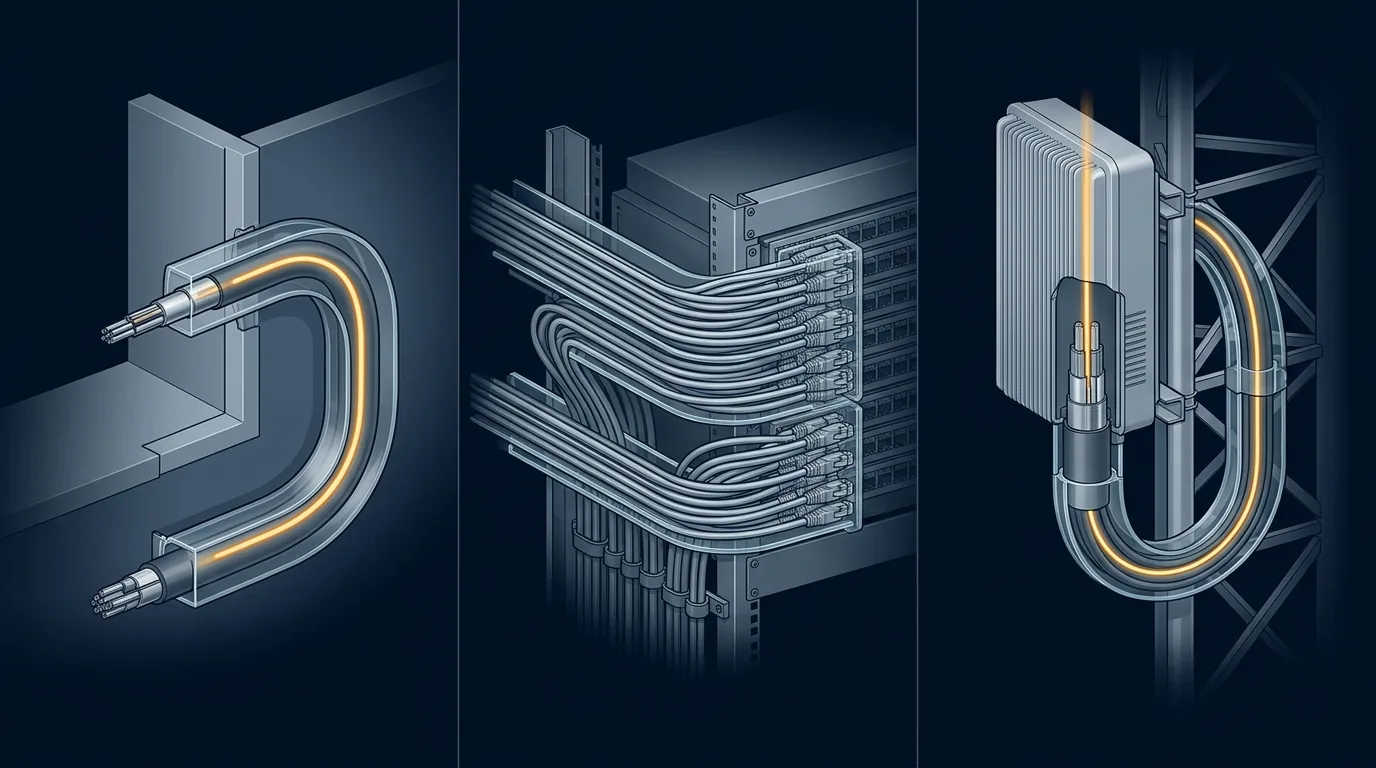
Same physics, three different risks: a tight service loop, a joint count, and a tower-top bend.
Four questions readers ask next
Can you explain how fiber optics work in a simple way?
Light enters a glass core at a shallow angle. Because the cladding around it carries light slightly faster, the boundary reflects the light back in instead of letting it through, and it keeps bouncing to the far end, where a detector reads it as pulses. That is total internal reflection optical fiber in plain English — no mirror, no electricity in the glass, just an index difference and geometry. It also covers how does fiber optics work and how does fiber optic work in two sentences, which is all the short version ever needs.
What is the downside to fiber optic?
It is fragile in ways copper is not, and it punishes handling. Exceed the bend radius and loss rises; exceed the pulling tension and you may have broken it without knowing; splice it badly and the test set tells you, not the drawing board. Splicing needs skill and calibration, and every passive link still depends on powered electronics at both ends — which is where the cost sits on short runs, not in the glass. Over a few meters, copper is often the more sensible answer.
How far can a fiber optic cable transmit?
It depends on the loss you will accept, so the honest answer is a calculation. In the 1550 nm window single-mode runs at roughly 0.2–0.3 dB/km, so twenty kilometers of cable contributes about 5 dB before any splice, connector or margin. In the 850 nm multimode window, at the 3 dB/km of OM1 and OM2-class fiber, loss reaches 3 dB — half the power — after a single kilometer. What usually stops a real link is the number of joints, and what sets the spacing between regeneration points is the terminal equipment, not the glass. Submarine and other undersea spans cross oceans on the same principle, using optical amplifiers along the route in place of electrical regenerators.
Do fiber optic cables carry electricity?
No. A fiber carries photons and nothing else, which is why it ignores electrical interference, why strands in one cable cannot crosstalk, and why there is no ground loop between two buildings. It also means you cannot tell whether a fiber is live by looking at it, and a laser at the far end is invisible and can damage an eye — so never inspect an unterminated end face without confirming it is dark. Power for the equipment travels on separate copper.
Where to go next
The mechanism is one page of physics; projects are not. If you are choosing cable now, work from the Fiber Optics 101 guide linked at the top of this page, then move to construction and spec: our outdoor fiber cable range lists the constructions built for duct, aerial and direct-buried routes, with the water-blocking, armoring and jacket options the last two sections turn into requirements.
And if you have a route in front of you and want a straight answer on which construction and which bend-insensitive fiber grade it needs, send it over — that conversation is faster than another round of reading.