
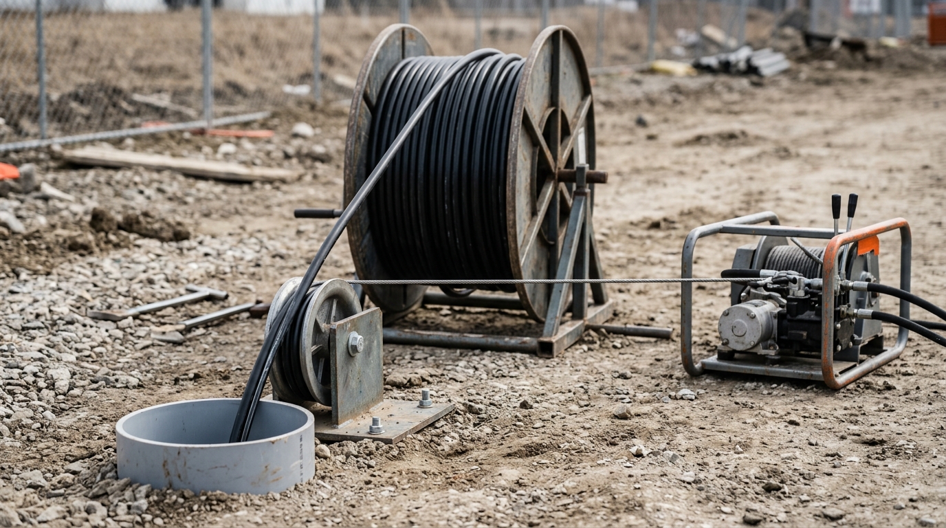
Installation
10 Fiber Optic Cable Installation Best Practices
Search for fiber optic cable installation and you get the residential answer: a technician arrives, drills one small hole through an exterior wall, mounts an optical network terminal, runs a speed test, and leaves. That visit is real, and if you are the customer it is the only part of the job you ever see — which is why most guides to fiber optic cable installation best practices stop at the wall.
Underneath it is a pull. Somewhere upstream of that wall, a reel of cable was paid off, threaded through a duct or lashed to a messenger wire, and dragged to the point where somebody could splice it. The failure modes that show up years later — a microbend that slowly drives attenuation up, a kink the crew felt but did not stop for, a jacket abraded at a manhole lip — are all created in that window.
What Fiber Optic Cable Installation Best Practices Have in Common
Every practice in the list below exists to keep one of four physical quantities inside the number printed on the reel you are pulling: tensile load, bend radius, torsion, and crush. Nothing else about a fiber optic cable installation damages a cable in a way that shows up later. Everything else — crew skill, equipment condition, weather, permitting — acts by pushing one of those four out of range.
That gives the list its order. The ten practices run the way a pull actually runs: plan, path, attach, limit, bend, twist, motion, protection, slack, support. A crew can lift the sequence straight into a method statement, and a spec writer can use it as the clause skeleton for an installation specification. Where a number matters, the number is given with the source that publishes it, because the governing figure is always the one on your own datasheet. If you want the wider discipline this sits inside, the fiber optic installation, splicing and testing handbook is the parent reference for this cluster; what follows is the pull itself.
1. Survey the Route and Budget the Pull Before the Cable Moves
A pull is an engineering event with a computed limit, not a test of how hard a winch can strain. The survey is where that limit gets set, and it is cheap, so do it properly and do it before the reel arrives. Everything the crew needs to know about cable pulling tension is fixed here, before a metre of cable moves.
Five things need to be on paper. Pathway continuity: can a rodder and mandrel travel the whole route, or is there debris, a collapsed duct, or a bend that no sheave will fit? Existing services: what is already sharing the duct bank, and at what clearance? Access spacing: how far is the longest unbroken pull, and where are the manholes and handholes that let you break it? Grade: duct runs are conventionally laid to a slight fall so water does not collect at a low point and freeze. Depth of cover: the burial depth for a new route is set by the owner, the franchise, or a permit — not by the cable — and the sibling article on how much cover a buried route needs works through that requirement in detail.
Then budget the force. Pulling tension is not one flat number; it accumulates as weight, friction, and every change of direction along the route. Corning's duct-installation procedure gives the number that surprises most planners: a three-foot offset in a ten-foot run of duct can add on the order of 120 lbf of tension to a pull (see the duct installation standard recommended procedure). A duct bank that passes the eye test can still be a hard pull because of offsets nobody measured.
Survey output | What you are deciding with it | Threshold to write down |
|---|---|---|
Longest unbroken pull length | Whether one pull is feasible or needs an intermediate assist | FOA: for outside plant runs beyond roughly 4 km (2.5 mi), pull from the middle toward both ends or use an intermediate puller |
Bend count and radius on the route | Tension accumulation and minimum sheave sizes | Every bend radius must exceed the cable's loaded minimum, or add a sheave |
Duct inside diameter and existing fill | Whether the cable fits inside the fill ratio | See practice 2 |
Reel length vs route length | Whether you can avoid a mid-route splice | Match reel to the run; a splice in the middle of a pull is a repair waiting to happen |
Locate tickets, permits, traffic control | Whether the job can proceed at all | Locate before you dig; a handhole or vault is a confined space if entry is required |
Temperature at pull time | Whether the jacket is at its stated installation condition | Check the datasheet's installation temperature range before you commit the crew |
Two safety items belong in the survey, not in the tailgate talk. Utility location is a legal prerequisite in most jurisdictions, and any work that involves climbing into a splice pit or vault has to be planned as confined-space entry with a rescue method that does not depend on the person inside.
2. Size the Conduit and Innerduct Before the Reel Arrives
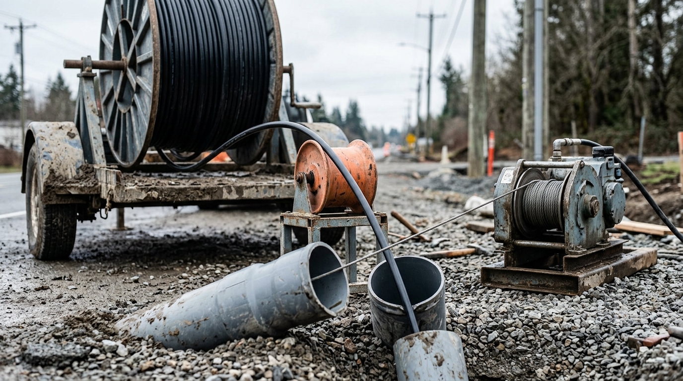
A pathway that was never sized for the cable sits behind a large share of damaged pulls. Fill ratio is the arithmetic that prevents it: the combined cross-sectional area of the cables, divided by the internal area of the duct.
Cables in the duct | Fill ratio, NEC basis | Fill ratio, Corning recommendation |
|---|---|---|
One | 53% | 65% (field-tested; Corning's own figure exceeds the NEC value) |
Two | 31% | 31% |
Three or more | 40% | 40% |
One code nuance saves a lot of argument on site. Where an optical fiber cable contains no current-carrying conductors, the NEC does not apply its raceway fill tables to it at all — the fill figures you design to come from the cable manufacturer's recommendation, and the code's role is about listing, separation and firestopping rather than percentage of area. That is covered in EC&M's walkthrough of Article 770. It also means the numbers above are engineering practice, not a code threshold you can point at; they still need to be on your drawing. Where a jurisdiction or owner sets a stricter limit, that limit governs the design — check the adopted code edition and the authority having jurisdiction before you commit to a duct size.
Work the sum properly and it decides the duct. Three 12 mm cables have a combined area of 339 mm². At 40% fill the duct needs at least 848 mm² of internal area, which is a minimum inside diameter of about 33 mm. In the common metric naming that is a 40/33 mm duct (40 mm outside, 33 mm inside) — the 1.5 in trade size, not the 25 mm (1 in) duct the trench already has.
Jam ratio is the second half of the sizing decision, and it has nothing to do with fill. If the ratio of the duct's inside diameter to one cable's outside diameter lands between 2.8 and 3.2, three cables being pulled into that duct can wedge against each other at a bend and stop the pull dead. Corning's engineering note on pulling fiber optic cable in conduit sets out the NEC's explanation of jamming and states that it concurs with the NEC's recommendation to prevent it. Two remedies follow from that, both of them sizing decisions rather than field fixes: change the duct size so the ratio falls outside the band, or pull the three cables as a triplexed assembly so they cannot cross over each other at a bend. A pull that stops with a bang is usually a jam, not a tension limit, and the fix was available weeks earlier.
Two more pathway items that are cheaper to fix before the reel than after:
- Innerduct. Subdividing a duct with innerduct gives you future pulls without a second construction permit. A common outside plant arrangement is three innerducts of 1.25 in inside diameter inside a 4 in duct — which only works if the host duct was sized with that end state in mind. Note that the 1.25 in here is the innerduct's inside diameter, a different measurement from the host duct's trade size.
- Rod, mandrel, and never over existing cable. Prove the pathway, clear it, then pull. Laying a new cable over one that is already in the duct is not recommended: the two rub, and a pre-existing cable is not something you want to be liable for. Where the route is direct-buried rather than ducted, the construction sequence changes — bedding, backfill and warning tape are their own discipline, covered in the comparison of choosing between a ducted and a buried route.
3. Pull on the Strength Members, Never the Jacket
Fiber optic cable is designed to be pulled, and it is designed to be pulled through one specific component: the aramid yarn or other strength member the manufacturer built into it for that purpose. Pull on anything else and the load path runs through the fiber and the jacket.
The hardware that makes this automatic is a pulling eye or pulling grip that attaches to the strength members and terminates in a swivel. The swivel matters as much as the attachment — it keeps the pull rope's residual twist from being wound into the cable as torque. Get the attachment point wrong and the fiber optic cable pulling force runs through the glass and the jacket instead of the yarn, which is exactly the load path the cable was built to avoid. The Fiber Optic Association's general installation guidelines are blunt about the ordering: pull by the strength members, use a swivel pulling eye, and do not pull by the jacket unless the manufacturer specifically approves it and an approved grip is used.
There is one documented exception, and it is narrow. Tight-buffered premises cable may be pulled by the jacket when a pulling mandrel of roughly 40 cm (8 in) is used — the cable is wrapped around the mandrel about five times and held gently, so the mandrel carries the load rather than the jacket. That is a premises technique for small cable, not a licence to hook an outside plant cable to a winch.
Reel handling is part of the same practice. Cable comes off a reel, not out of it. Rolling the reel or using a payoff stand lets the cable pay out straight; pulling cable off the end of a stationary reel puts one twist into the cable for every turn of the drum, and those twists accumulate into a tangled, kinked pull no winch operator can recover.
4. Set the Pull Limit From the Datasheet and Monitor It
Here is the number most crews have never seen: for stranded loose tube and ribbon cable, the maximum pulling tension is commonly 600 lbf (about 2,700 N). Both Corning and Prysmian publish that figure for their standard outside plant cable, and [Prysmian's underground installation practices](https://na.prysmian.com/sites/na.prysmian.com/files/media/documents/Install 05 Underground Cable Installation Practices Iss 3.pdf) state it as a hard rule rather than a target — never exceed 600 pounds, and run the winch or capstan with a tension monitor so the operator can see where they are against it. Corning's duct-placing procedure says much the same in different words: except for short runs or hand-pulls, tension must be monitored, and a winch with a calibrated maximum tension is an acceptable way to do it.
That figure is a starting point, not a universal constant, and this is the trap. Cable construction drives the limit: a stranded loose-tube OSP cable and a flat drop cable of similar diameter do not carry the same rating, and micro cable lower still. The governing document is always the specification sheet for the reel in front of you — which is why the datasheet should be on site, not in an office. Exceeding the rated tension voids the cable warranty, and the damage does not announce itself; it shows up as loss at acceptance testing or, worse, as a fiber that fails two winters later.
Limit | Value | Published by | Applies to |
|---|---|---|---|
Max pulling tension | 600 lbf (2,700 N) | Corning, Prysmian | Standard stranded loose tube and ribbon OSP cable |
Max pulling tension | Check the datasheet | Cable manufacturer | Drop cable, micro cable, tight-buffered premises cable — materially lower |
Monitoring | Required except short runs and hand-pulls | Corning | Any powered pull |
Breakaway device | Swivel with a set breaking load | Corning, Prysmian, FOA | Long pulls, where the winch operator cannot see the reel |
Sidewall pressure | Rises with tension at every bend | Corning | Long pulls through multiple bends — split or assist the pull |
Tension that accumulates past the limit is not a reason to slow the winch down; it is a reason to change the plan. The three things that push a pull toward its ceiling are all measurable before the crew arrives, and each one has a planning answer:
What raises the tension | Why | Planning answer |
|---|---|---|
Route length and friction | Every metre of cable and duct wall adds to the force the winch has to overcome | Pull lubricant, a smooth continuous pull, or split the route at an existing access point |
Offsets and bends in the duct | Each change of direction adds tension — practice 1 gives the figure for a single offset | Count the offsets during the survey; add an intermediate assist rather than accepting a higher reading |
Several bends in one long pull | Sidewall pressure — the crushing force where the cable bears on the inside of a bend — climbs with tension | Split the pull into shorter legs, or use an intermediate puller so no single leg carries the whole force |
For outside plant work, the practical threshold for adding an assist is route length itself: on runs beyond roughly 4 km (2.5 mi), the standard approach is to pull from the middle toward both ends, or to work from an intermediate point with an automated puller, rather than to attempt one heroic pull. Deciding that during the survey costs nothing. Deciding it after the winch has stalled costs a re-pull.
One row above is worth a sentence of its own. A breakaway pulling swivel set below the cable's rating is a fail-safe: the pull physically cannot exceed the limit even if someone at the winch is not watching the meter. Treat it as exactly that — a backstop — rather than as the way you find out what the tension is. The number you are managing against still has to come from a monitored winch or a tension meter, because a breakaway link that trips is already an event you have to explain.
5. Hold 20× Diameter Under Load and 10× at Rest
The bend radius rule every installer is taught is 20 times the cable diameter while the cable is under tension, and 10 times the diameter once it is installed and relaxed. Two details are routinely lost.
The first is that the rule produces a radius, and the hardware you buy is specified by diameter. If a cable must not be bent tighter than 20× its diameter, then a pulley or capstan it runs over needs a diameter of 40× the cable diameter — double the number, because radius and diameter are different quantities. The Fiber Optic Association keeps a dedicated reference on the radius/diameter confusion precisely because it keeps producing wrong hardware orders, and it is the reason to state limits in the units the crew actually measures.
The second detail is that 20×/10× is a default, not a specification. The published requirement in GR-20 and ICEA-640 for ordinary cable is 20× the outside diameter while loaded, but some cable constructions are rated at 15×, and Corning's direct-buried installation procedure works its own installation example — the working radius you calculate with — at 15× rather than 20×, which is why the sentence on the datasheet matters more than the rule of thumb. When no manufacturer recommendation is available, the consensus standard falls back to the 20×/10× pair — that fallback is written into ANSI/NECA/FOA 301. When one is available, it wins.
Cable diameter | Min bend radius under load (20×) | Min sheave/pulley diameter (40×) | Min installed bend radius (10×) | Min storage loop diameter (20×) |
|---|---|---|---|---|
6 mm (0.25 in) | 120 mm | 240 mm | 60 mm | 120 mm |
13 mm (0.5 in) | 260 mm | 520 mm | 130 mm | 260 mm |
20 mm (0.75 in) | 400 mm | 800 mm | 200 mm | 400 mm |
25 mm (1.0 in) | 500 mm | 1,000 mm | 250 mm | 500 mm |
All four columns come from the same multiplier of the same cable diameter, which is why a single field error doubles or halves a limit. The outside diameters to plug into it are tabulated in the site's cable diameters for the 20× rule. The independent treatment of how bend radius varies by cable construction, and what exceeding it does to the light itself, lives in the sibling article on how the bend radius tightens under load — this practice states the pull-side rule; that one proves the consequence on a test set.
6. Take the Twist Out: Figure-8, Reel Rotation, Torsion Limits
Torsion is the quantity nobody measures, because nothing on the truck reports it. It is also the one that turns a clean pull into a birdcage.
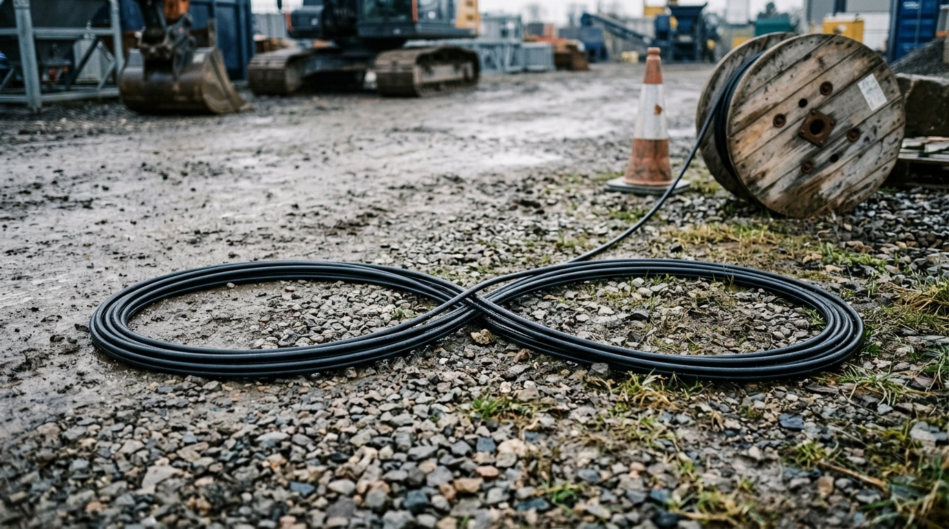
Three rules cover it. Pull from a swivel so the rope cannot wind torque into the cable. Roll the cable off the reel rather than spinning it off the end. And when you lay cable out on the ground for a long pull, lay it in a figure-8: the pattern puts a half twist in on one side of the eight and takes it out on the other, so the net twist is zero. The Fiber Optic Association describes both the swivel and the figure-8 as standard practice in its installation guidelines.
The figure-8 is also how you do a mid-span access on a long pull. When a run is too long for one continuous pull, the crew pays the cable out along the first leg, figure-eights the surplus at an intermediate point, pulls the first leg home, then pulls the remainder from the far end out of the figure-8. This is the documented alternative to a single heroic pull, and it is why the figure-8 layout is worth teaching as a technique rather than treating as improvisation.
One warning belongs here, because it is easy to violate with equipment that looks helpful: automated figure-eight machines that coil cable onto a drum can exceed the cable's torsion, tension, and bend-radius limits at the same time. Corning's direct-buried procedure says plainly not to use them on central-tube cable or on loose-tube cable with corrugated steel armor. A machine that speeds up payoff is not worth discovering this with.
7. Keep the Pull Smooth: Lubricant, Speed, No Surging
Friction is what the winch is really fighting, and it is the one variable you can change cheaply. Cable lubricant is recommended for most fiber pulls and will noticeably lower the tension required to complete one; short hand-pulls are the exception. The compatibility question is not optional — a lubricant that attacks the jacket material costs more than it saves, so the choice is made against the jacket compound, not against whatever is in the van.
How you apply the pull matters more than most crews expect. [Prysmian's underground installation practices](https://na.prysmian.com/sites/na.prysmian.com/files/media/documents/Install 05 Underground Cable Installation Practices Iss 3.pdf) are explicit that surges and stops during a pull should be kept to a minimum and avoided altogether if possible — a cable that is stopped mid-duct has to overcome static friction to restart, so the restart spike is often the highest tension of the whole operation. A slower continuous pull ends up kinder to the cable than a fast one with pauses in it. On very long runs, an automated puller with tension control, or a puller working at an intermediate point to make the pull continuous, is the standard answer.
Where the pathway allows it, there is a third option that removes most of the pulling problem instead of managing it: blowing or jetting cable into a microduct. It replaces tension with air drag, works well over long duct runs, and needs a cable designed for it — the air-blown micro cable family is built for exactly this, and the site's air-blown micro cable installation range is where that construction is specified. A duct that is right for jetting and a duct that is right for pulling are not always the same duct, so this is a design decision, not a field swap.
8. Protect Every Bend, Duct Mouth and Building Entry
Pulls rarely fail in the middle of a straight duct. They fail at the transitions, where the cable is asked to change direction or pass an edge.
The hard cases are the ordinary ones: the lip at the end of a conduit, the edge of a manhole, the point where a cable leaves a duct and enters a handhole. Anywhere the cable is dragged across a sharp corner it conforms to that corner, and conforming to a corner means a bend radius far tighter than the cable's rating. Corning's engineering note names manhole edges and conduit ends as exactly this category, and points to the fix as equipment designed specifically for fiber rather than for electrical cable. The Fiber Optic Association's installer reference is more concrete about what that equipment is: sheaves, quadrants or flexible ducts wherever the run changes direction, so the cable bends to the hardware's radius instead of a duct lip's. Hardware chosen for power cable is a common and expensive mismatch.
Inside a building, three separate requirements land at once:
- Firestopping. Where cable and raceway pass through a fire-rated wall, partition, floor or ceiling, the penetration has to be firestopped to the rating of the assembly, following the manufacturer's instructions for that cable type and construction.
- Point of entrance. Underground or outside plant innerduct entering a building has to be terminated and firestopped where it crosses the entrance; the short-length exception for unlisted cable is 50 ft (15 m) and applies only where the cable terminates in an enclosure or is run in a metal raceway. If the design depends on that exception, say so on the drawing.
- Separation from power. Not every fiber cable follows the same rule. Whether an optical fiber cable may share a raceway or cable tray with power conductors turns on whether the cable is conductive or all-dielectric, and on whether a conductive cable has an armored or metal-clad sheath — the exemption that permits sharing is written around specific sheath constructions, and a cable that lacks them is held to a stricter rule unless a permanent barrier or listed divider separates it from the power conductors. That matters commercially as well as technically: armored cable is often chosen for rodent and crush resistance, so the cable you specified for toughness can sit in a different clause from the dielectric cable the route was designed around. Check the requirement against the code edition the project is built to instead of assuming the two cases behave alike.
9. Leave Slack at a Reachable Radius — Handholes, Splice Points, Service Loops
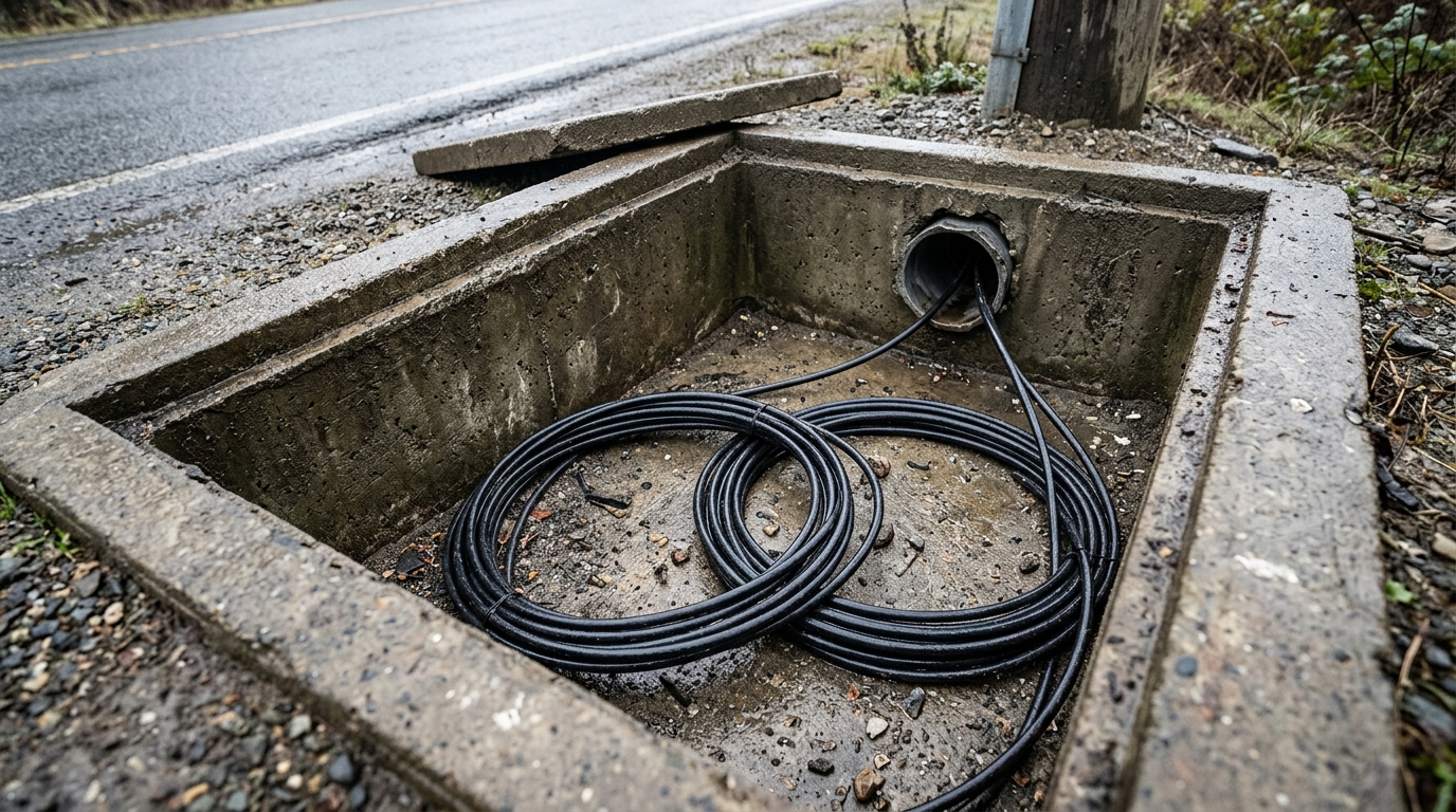
Slack is not waste. It is the allowance that lets a closure be lifted to a splicing table, lets a damaged span be re-spliced without pulling a new hundred metres, and lets someone open a joint in five years without cutting a working cable to get the loop out. The work that happens inside that loop — splicing the cable at a slack point — is its own discipline, and it is the reason the loop exists.
The amount is set by the operations that will need it. Corning's direct-buried installation procedure specifies a minimum of 33 ft (10 m) of cable on each end at every splice point, sized so the splice vehicle can actually reach the cable. The same procedure puts slack in the handhole horizontally rather than coiled vertically, where it fights gravity and slowly sags against the closure.
The dimension that decides whether your slack is safe is the loop diameter, and it is derived, not guessed. The installed bend radius is 10 times the cable diameter; a loop is a bend of 360 degrees, so the loop diameter has to be at least 20 times the cable diameter. For a 13 mm cable, that means a minimum loop diameter of 260 mm — a coil you would not accidentally make too tight by hand, and one a crew can check with a tape.
Slack needed | Cable OD | Min loop diameter | Cable per loop | Loops to coil |
|---|---|---|---|---|
10 m (33 ft) | 13 mm | 260 mm | 0.82 m | 13 |
10 m (33 ft) | 20 mm | 400 mm | 1.26 m | 8 |
20 m (66 ft) | 13 mm | 260 mm | 0.82 m | 25 |
Two practical notes. Coiling more slack means a bigger coil, not a tighter one — if the coil will not fit the handhole at the required diameter, the handhole is the problem, not the slack. And any work that involves climbing into the handhole or vault to dress that slack is confined-space work with an entry plan, not a five-minute job.
10. Support the Slack: Aerial Loops, Risers and Vertical Runs
The same slack, in the air or in a riser, has to be supported rather than stored.
Aerial. Cable lashed to a messenger, or self-supporting figure-8 cable — the cable construction, not the ground-laid payoff pattern in practice 6 — carries its own service loops on the pole. Those loops are held by brackets — commonly the flat "snowshoe" type suspended from the messenger — and the bracket exists to keep the loop from hanging open and pulling the cable below its minimum bend radius. A loop that has lost its bracket, or was never fitted with one, is a bend-radius violation waiting for a load to reveal it. Pole spans, sag and loading are governed by the owner's construction standards; in the United States the federal reference for aerial plant design is the RUS bulletin series, including 1751F-630 for aerial plant and the companion underground plant design bulletin.
Risers and vertical runs. Drop the cable down rather than pulling it up wherever the geometry allows, and support it at frequent intervals so the jacket is not carrying the cable's own weight over a long fall. Cable ties are the subtle hazard here: fiber is sensitive to compressive load, and a tie tightened with an installation tool can crimp the jacket and impose a permanent bend. Ties should be snug enough to hold and loose enough to slide along the jacket by hand, with the tail cut off so nobody can tighten it later; hook-and-loop fasteners are the safer default because they cannot apply that much crush force. Where a run is genuinely long and vertical, a support grip does the load-bearing job.
The last mile is where these habits pay off fastest, because drop cable is the highest-volume cable on any access build and the easiest to abuse — the guide to installing the last-mile drop covers the cable types and where each belongs.
Write Down What You Pulled and Hand Over a Testable Plant
The ten practices above are all decisions, and a decision that is not recorded is not a decision the next crew can rely on. Close the pull with a record that answers the questions someone will ask in five years: which reel went into which segment, what the highest tension reading was, where every slack loop is and what diameter it was coiled to, where the splice points are, and what the acceptance test showed.
That record is what makes the cable plant maintainable. It is also what turns a pull from an act of skill into a repeatable procedure — the same numbers, the same limits, the same hardware, whether or not the same foreman is on site.
The proof that the pull was clean arrives at acceptance testing, and it arrives as a measurement rather than an opinion. The next step in this cluster is that test: the acceptance test that proves the pull covers the OTDR and insertion-loss work that verifies the plant you just installed. If you are specifying a pull and want the tension and bend figures for a specific cable construction before the route is finalised, DYS's outdoor and duct fiber cable range publishes them per construction — and the datasheet for the reel you are pulling is always the number that governs.