
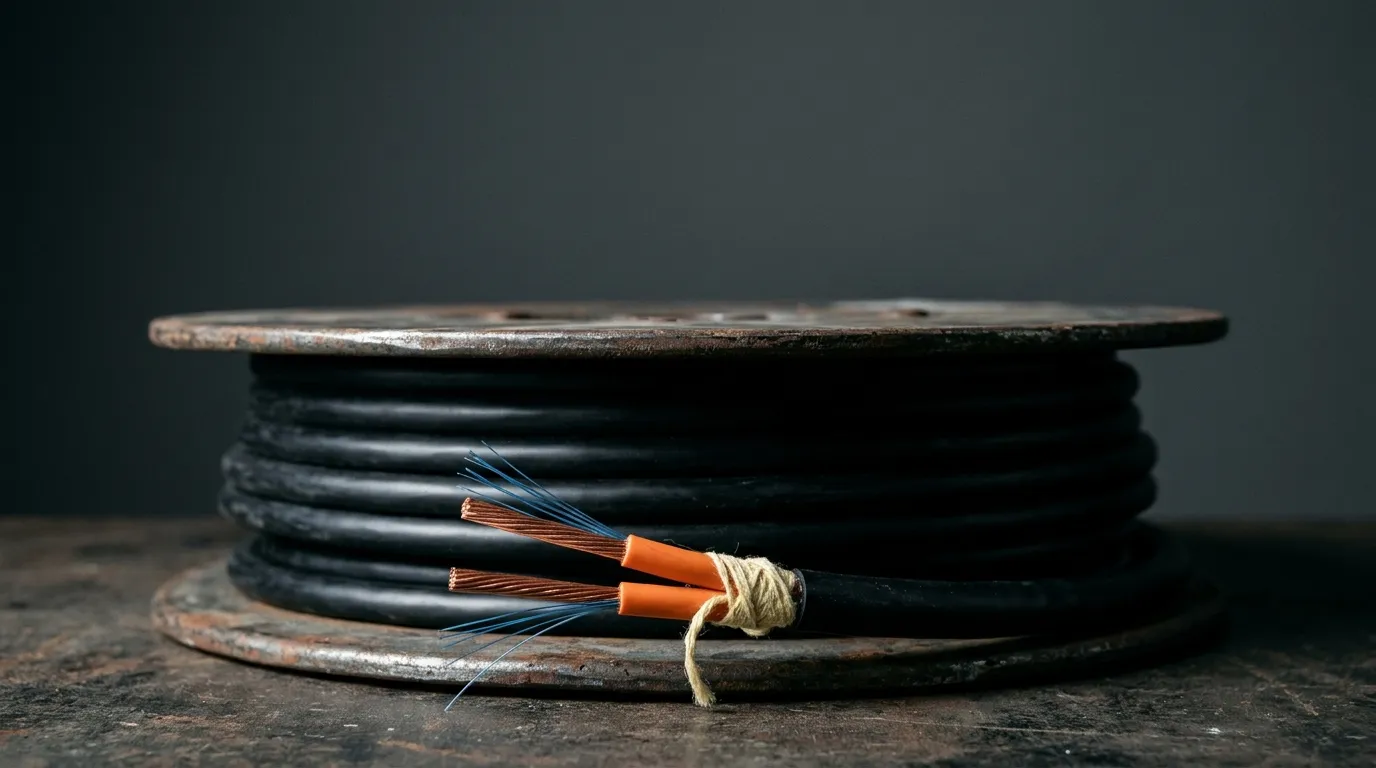
FTTA / 5G
Hybrid Fiber Power Cables for 5G Small Cells
A 5G small cell needs two things that used to arrive on two different cables: a small cell backhaul link to the network, and DC power for the radio. Hybrid fiber power cables put both inside one jacket, so a crew pulls, clamps and terminates once instead of twice. That single decision changes the civil works, the pole load, the electrical design and the RFQ. It also creates a specification problem most buyers underestimate, because the copper half has a hard distance limit that has nothing to do with how far light travels.
This guide covers what the term means, what sits inside the jacket, how far the copper really reaches on a 48 V plant, how to design the pole run, and what to put in a purchase order.
What a Hybrid Fiber Power Cable Is — and the Three Products It Gets Confused With
A hybrid cable contains optical fiber and current-carrying copper in one overall sheath. That is the definition the standards bodies settled on, and it is narrower than the way the term gets used in the wild. Belden's 2024 summary of those definitions records four organisations converging on one product, though not on one sentence: TIA calls it a cable with both optical fiber and current-carrying members, NEC a cable with optical fibers and current-carrying electrical conductors, and ICEA both optical fibers and metallic conductors. ISO's is the broader one — an assembly of two or more cable units and/or cables of different types or categories in an overall sheath, which may include an overall screen — covering the construction without naming the conductors. In procurement the same product turns up as hybrid fiber cable, hybrid fiber optic cable, hybrid copper fiber cable or powered fiber cable; this article uses hybrid fiber power cables throughout.
Three neighbours get mixed in, and one is a completely different product.
Product | What it carries | Typical job | Why it is not the same |
|---|---|---|---|
Hybrid fiber + copper | Optical fiber and DC power | Small cell, camera, Wi-Fi AP, DAS node | The reference product for this article |
Composite cable | Two variants of one medium (SM + MM fiber, or shielded + unshielded pairs) | AV racks, multi-signal runs | No power conversion, same signal family |
Hybrid fiber-coaxial (HFC) | Optical fiber and coaxial RF | Cable-TV and DOCSIS access networks | RF, not DC power — a plant, not a drop |
Power over fiber | Light, converted back to electricity at the far end | High-voltage-isolated sensors | No copper at all, and very low wattage |
The HFC confusion is live in today's results, where at least one supplier explainer describes a "hybrid fiber optic cable" as fiber plus coaxial. If you are ordering for a radio site and someone quotes HFC hardware, the conversation has gone wrong somewhere.
For a small cell the first row is the only relevant one, and there the fiber is a normal single-mode link — the same physics as any other FTTA fiber run, just sharing a jacket with a power pair.
Why a Small Cell Wants One Pull, Not Two
A small cell is a radio, a modem and an antenna in a box the size of a shoebox, mounted where the traffic is: lamp posts, bus shelters, the side of a building, a metro pillar. It has no equipment room, no cable tray and usually no spare conduit. The GSMA's small-cell deployment guidance puts the capacity requirement at 100–200 Mbps per cell and is blunt about the civil side: backhaul can come from point-to-point microwave or from fiber, and installing fiber links is disruptive and expensive, which is why deployments cluster where duct already exists.
That economics is what makes the single-pull argument work. One cable means one trench, one duct occupancy, one set of pole clamps, one weatherproof entry into the enclosure, and one item in the storeroom. Panduit's Opti-Core hybrid powered cable makes the same case on its product page: one cable for data and power, no separate runs.
There is a structural argument too. On a macro tower there is room to run fiber and power as separate cables up the same steel, and that is what most towers do. A pole-mounted small cell has a much tighter envelope: smaller clamps, a smaller wind-load budget, and every extra cable is another snag point for ladders, vehicles and vandals.
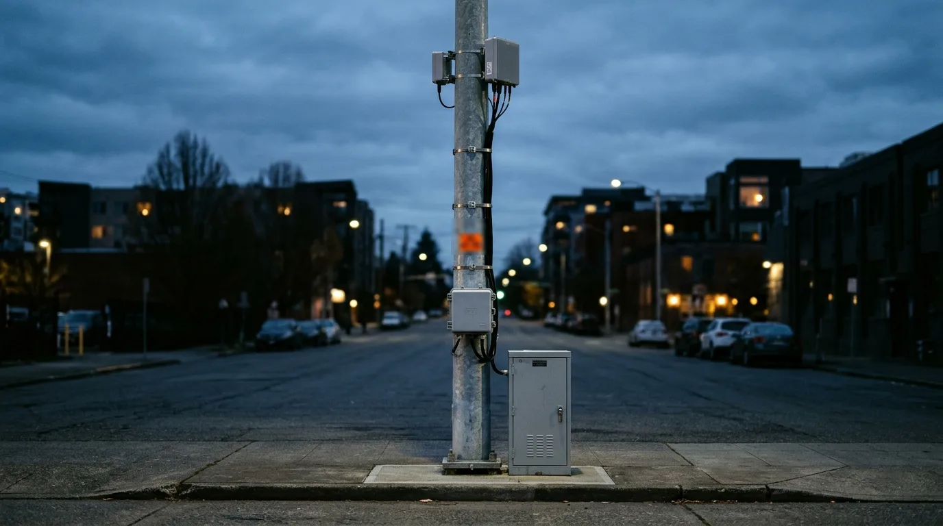
The radio sits high, the junction box at working height, and the cabinet at the base is where the DC plant and the fiber feeder meet. Two cables would mean two runs up the pole and two entries into the box.
Three cautions before the cable choice becomes a decision. Power still has to come from somewhere — a hybrid cable moves a supply, it does not create one, and a pole with no electricity is an electrical project first. The copper sets the reach, not the fiber: a single-mode link runs kilometers, the pair in the same jacket does not. And two cables are sometimes the right answer: if the pole already has a DC feed and a fiber drop, if the structure cannot take the extra weight, or if nobody wants a metallic path up a pole in a lightning-prone area, keeping fiber and power separate is cheaper than retrofitting a hybrid. The one-pull case is strongest on new builds and on shared street furniture, where every added cable needs permission.
Where this sits inside the wider FTTA and 5G fiber stack is worth a look if this is your first small-cell build.
Inside the Jacket: Reading a Hybrid Cable Datasheet
The two halves follow different design rules, so a hybrid datasheet reads like two datasheets stapled together. The fiber side looks familiar — 900 µm buffered fiber in a 2 mm subunit, aramid yarn for tensile strength, sometimes corrugated steel tape for rodent and crush protection, then the jacket. Proterial's Power+ construction is a 900 µm buffer inside a 2 mm subunit, with 2, 6 or 12 fiber strands and a single pair of 12, 14, 16, 18 or 20 AWG stranded conductors, rated indoor/outdoor plenum and listed as UL CMP-OF / CL3P-OF.
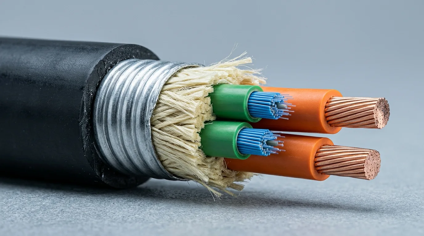
Each layer answers a site problem. The armor takes crush and rodent damage on a pole run. The aramid carries pulling tension so the fibers do not. The jacket decides UV life and fire performance — polyethylene outdoors, LSZH where a cable enters a building, TPU where abrasion is the enemy.
Then the copper side, where the numbers matter. Vendors file the same construction under several names — Fluke calls it hybrid copper-fiber cable, Proterial sells a composite fiber cable, Panduit a hybrid powered cable — so check the construction rather than the label.
- Conductor size. Fluke Networks puts the conductors in commercial hybrid cable at 12 to 20 AWG, with anywhere from two conductors for a single device up to twelve for a multi-device remote power scheme. AWG is not a detail; it decides how far the run can go.
- Conductor count. One pair is the common case for a small cell: positive and negative from a DC plant.
- Circuit class. The copper typically delivers non-PoE Class 2 power, and some constructions reach Class 3 for heavier loads. Fluke's field guide is unusually clear that PoE is a balanced-twisted-pair protocol, supported to 100 m, and that a Class 2 circuit is not automatically PoE. A small cell fed from a 48 V rectifier is a DC circuit, not a PoE port.
- Fiber grade. For a pole with tight cable management, bend-insensitive single-mode fiber is the sane default; ITU-T G.657 defines those bending-loss classes, and the difference shows up when someone coils 2 m of slack into a 300 mm enclosure.
Fiber count deserves its own note. Two fibers cover a small cell today and leave no spare; twelve cover the radio plus a second sector, a camera or a Wi-Fi backhaul on the same pull, at the cost of a thicker cable and a bigger bend radius. Panduit sells both 2- and 12-fiber versions of the same hybrid product for exactly this reason. If the pole is likely to be revisited, buy the spare fibers now — pulling a second cable later costs more than the fiber did.
How Far the Copper Actually Goes
This is where hybrid design surprises people: the one part where the two halves disagree.
Fluke's guide quotes the vendor endpoints: Corning composite cable with 12 AWG conductors delivers 75 W to roughly 457 m, while the same 75 W on 20 AWG reaches about 71 m. Note the ratio between those distances, 6.4 to 1, against the ratio of copper loop resistance between 12 and 20 AWG, 6.40 to 1. That is the signature of a voltage-drop limit, not a thermal one: the cable is not overheating at 71 m, the radio is simply seeing too little voltage.
Once you know the mechanism the arithmetic is short. For a two-wire DC loop, drop is 2 × current × resistance × length. Fix a voltage budget and the maximum distance falls out. The table below uses 48 V DC, a 10% drop budget (4.8 V), and standard annealed copper at 20 °C.
Conductor | Loop resistance per 100 m | 1 A (48 W) | 1.5 A (72 W) | 2 A (96 W) |
|---|---|---|---|---|
12 AWG | 1.04 Ω | 461 m | 307 m | 230 m |
16 AWG | 2.63 Ω | 182 m | 121 m | 91 m |
20 AWG | 6.66 Ω | 72 m | 48 m | 36 m |
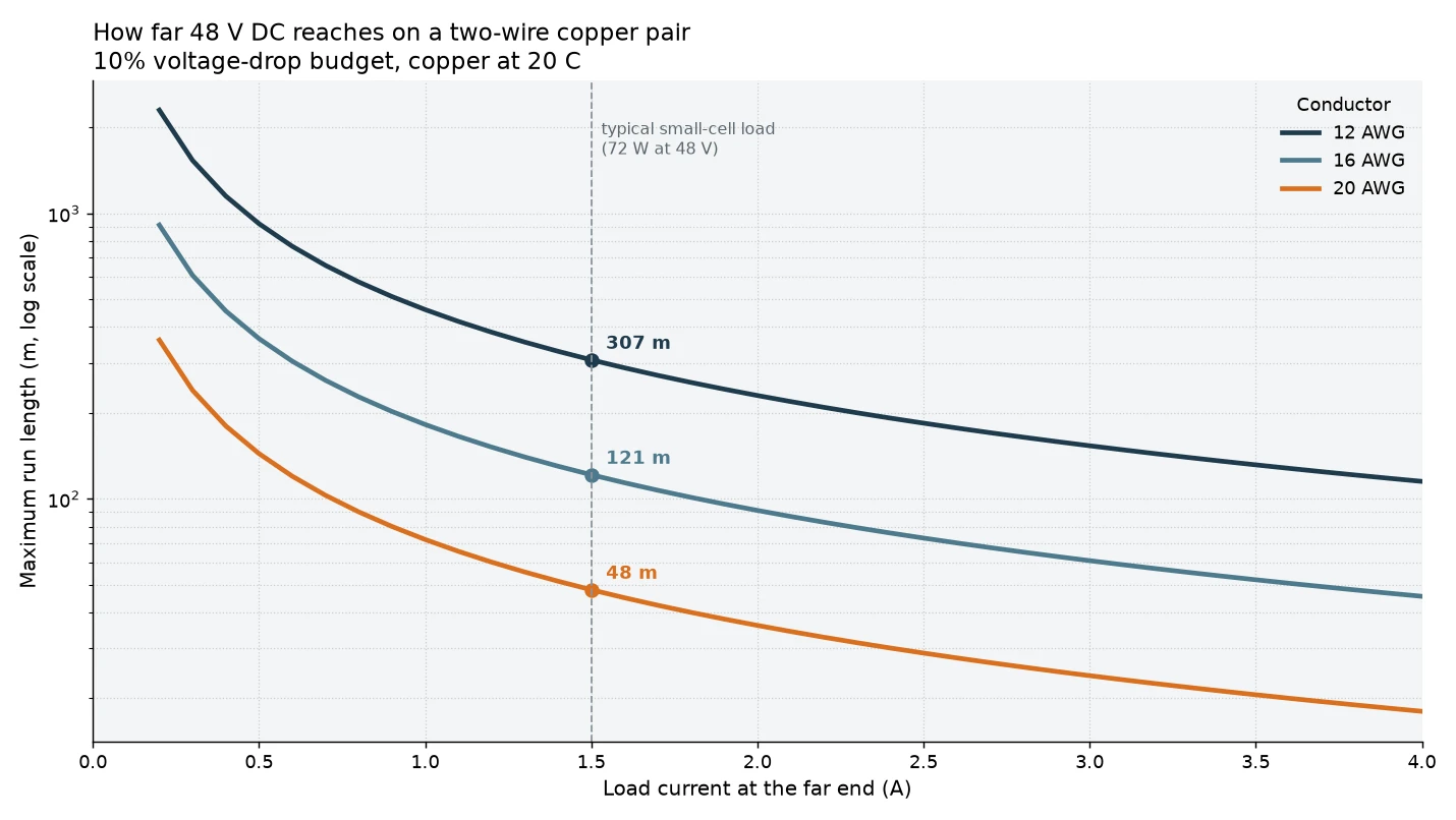
Read that as a design warning, not a warranty. The figures assume constant current; a radio with a DC-DC converter draws near-constant power instead, so as voltage sags the current climbs and the run ends up one drop budget shorter — about 10% at the 10% budget this table assumes, which turns 461 m into roughly 415 m. Two other things move the numbers: the actual supply voltage at the cabinet rather than the nominal one, and temperature, since copper resistance climbs as the cable heats in sun. A pole-mounted run in a hot climate with a loaded pair is the worst case, and it is also the most common case for a small cell.
Change the budget and everything rescales: at 5% instead of 10%, every distance in the table roughly halves.
Size the copper for the load you will have, not the load you have now: a radio drawing 60 W today may be replaced by a 90 W unit in three years, and the cable is the one component nobody wants to re-pull. Fluke is direct about the alternative — when pre-planning is wrong and the distance too long or the conductor too small, the remedies are replacing the cable, shortening the circuit or swapping the device for a lower-power one.
Designing the Run: Pole, Cabinet, Ground, Surge
A hybrid cable adds a copper pair to a structure that previously carried only glass. That changes the electrical safety case, and it is the part of the design most often left to whoever shows up on site.
Bond and ground the copper path. A metallic pair running up a steel pole is a path for fault current and lightning-induced surge. The armor or shield and any metallic enclosure need bonding to the structure's grounding system per the local electrical code, and the DC pair needs surge protection at the cabinet end. This is not a fiber-only installation any more; treat it as an electrical installation that happens to contain fibers.
Keep the power entry and the fiber entry separate. Bring the copper in through the power gland with proper strain relief, and leave the fiber in its own path so a future re-termination does not disturb the DC side.
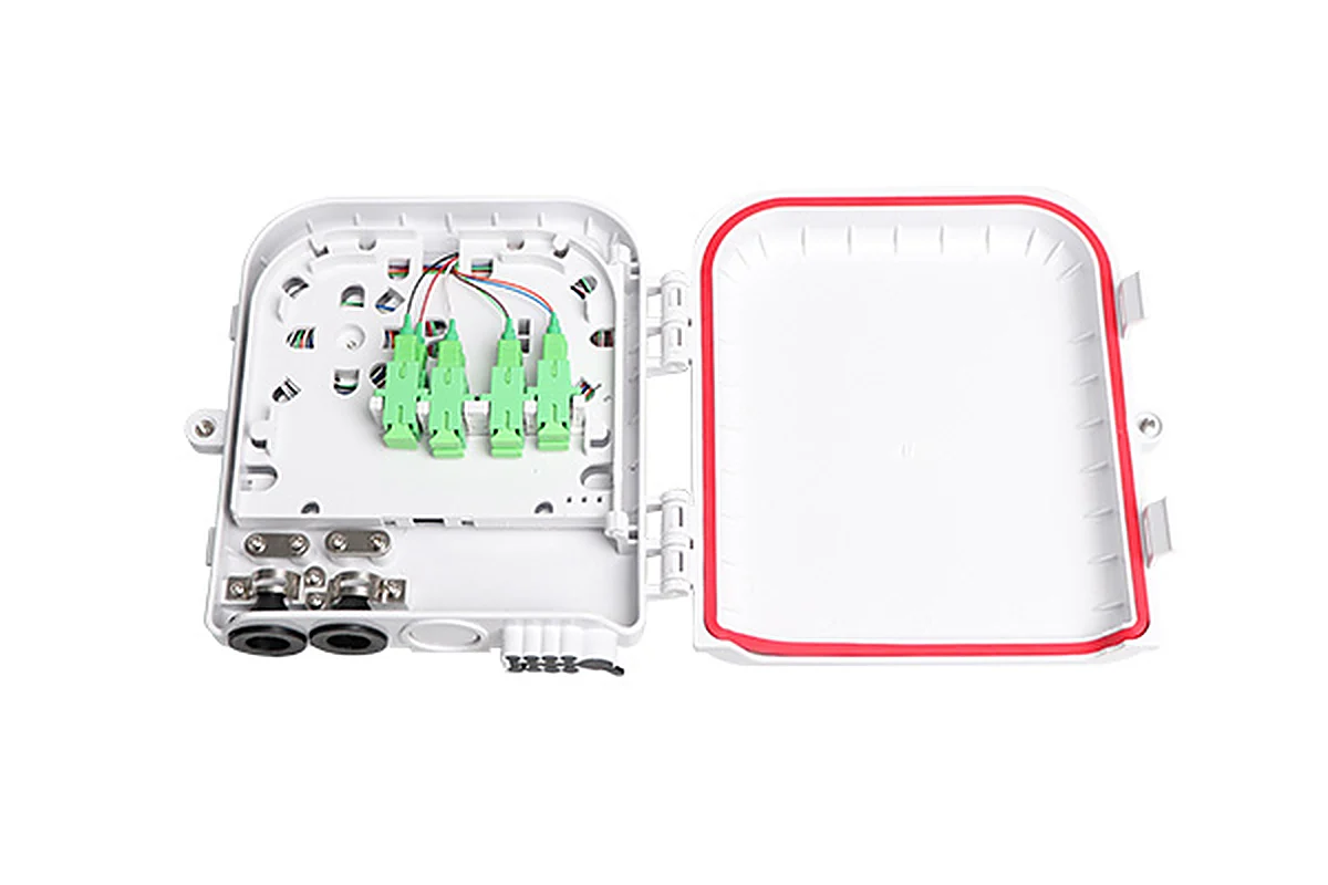
The open box shows the constraints: adapters, a gasket rated for a decade of weather, and glands that decide how many cables it takes.
Check the IP rating against the site, not the catalogue. A pole-mounted box faces driving rain, pressure washing and, near a coast, salt. The rating is what keeps water out of the fiber path, and the difference between IP67 and IP68 — and what each is tested against — matters before you specify; we covered it in IP67 vs IP68 outdoor fiber connectors.
Bends are the other silent failure. A tight coil behind a small enclosure is the classic cause of a bend loss that only shows on the OTDR, which is why the bend radius rules belong on the checklist next to the torque figures.
Watch the load on the pole. Cable weight and wind area are part of the asset owner's structural budget. A hybrid cable is heavier than the fiber drop it replaces, and a 12-fiber 12 AWG construction is heavier again. Mid-span clamps should hold the cable without crushing the jacket.
In Europe, fire performance is a purchasing gate. Cables sold for construction works fall under the Construction Products Regulation, and the harmonised rules for marketing construction products require a declared reaction-to-fire class. For fiber and hybrid cable that means the EN 50575 Euroclass system, which we unpacked in CPR fire ratings for fiber cable in the EU.
Specifying the Fiber Half — and What DYS Builds
Most projects do not buy a hybrid cable as a catalogue part. They buy the fiber side as a specified construction and the copper side as an electrical requirement, and the two meet in one jacket at the factory.
The fiber element for a small cell looks much like the fiber to the antenna (FTTA) indoor/outdoor cable already used on macro sites. In the DYS FTTA range, the GJYWFJH construction is a 900 µm subcable with a layer of aramid yarn over it and an outer jacket in PVC, LSZH, TPU or PE to the customer's requirement. The two-fiber version measures 4.8 mm OD and 28.3 kg/km, and is rated 600 N short-term and 300 N long-term tensile, 1000/500 N per 100 mm crush, 20D dynamic and 15D static bend radius, with a −40 to +70 °C working range. Add steel tape armor and the same family becomes GYFJH53 at 8.2 mm OD with 800/500 N tensile for rodent-prone or armored routes.
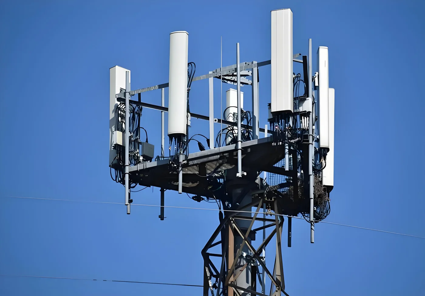
What DYS supplies for a small-cell project is that fiber half plus terminations — waterproof assemblies, IP-rated connectors and outdoor enclosures — and, on OEM/ODM work, a cable built to the customer's drawing rather than to a catalogue page. If the project needs a single-jacket hybrid with a copper pair inside, start with a spec-level enquiry: fiber count and grade, conductor size and count, jacket material, fire rating, OD ceiling, termination. That is a buildable brief; "hybrid cable, 12 fiber" is not.
For the connector end, ODVA, NSN-style boots, FullAXS-style bodies and PDLC change the enclosure interface and the maintenance routine, and we compared them in FTTA cable assemblies compared. Hybrid cable does not change that decision — it means the same connector family has to coexist with a power gland on the same box.
An RFQ Checklist for Hybrid Fiber Power Cables
Send every supplier the same sheet and the quotes become comparable. Nine lines cover most small-cell projects.
- Fiber count and grade — 2, 6 or 12; G.657.A2 or G.652.D; single-mode only, or a multimode leg.
- Conductor size and count — AWG per the voltage-drop calculation, one pair or more.
- Voltage and load — nominal DC voltage at the cabinet, steady-state watts at the radio, acceptable percentage drop.
- Run length — route length including vertical rise, plus slack at both ends.
- Jacket and fire rating — PE, LSZH or TPU; the Euroclass or UL listing the site requires.
- Mechanical limits — maximum OD, minimum bend radius, tensile and crush figures the route demands.
- Termination — connector type at each end, pigtail or pre-terminated, and whether assemblies are tested before shipment.
- Environment — UV, burial, salt, rodent risk, operating temperature range.
- Acceptance evidence — insertion and return loss per fiber, continuity and resistance per conductor, and the report format.
Two lines are usually missing from buyer templates and cause the most rework: the drop budget in line 3, and the acceptance evidence in line 9. A supplier who cannot state both is telling you something about how the cable will arrive.
Acceptance Testing Before You Energize
Test the two halves separately, because they fail for different reasons and one test cannot see the other.
On the fiber side, treat the link like any other single-mode span: Tier 1 loss testing with a source and power meter, or an OTDR trace when you need to prove where a problem is. Both at the wavelengths the radio uses, with results logged against the link budget in the handover pack.
On the copper side, a digital multimeter answers the three questions that matter: continuity end to end, voltage at the far end under load, and loop resistance to confirm you got the conductor size you ordered. If the radio browns out under transmit, measure the drop under load rather than at idle — an idle radio draws a fraction of its peak current.
Then walk the installation while the enclosure is still open. Clamps not crushing the jacket, bend radii respected at both ends, glands sealed, bonding conductor landed, spare fibers coiled at a radius the box can actually accommodate. That ten-minute inspection is cheaper than a return visit, and on a street asset a return visit usually means a permit.
If you are still choosing the construction and the connector family for a small-cell programme, send us the site list and the electrical requirements and we will quote the fiber side against them.