
Data Center
Fiber for AI Data Centers at 800G: MFD, IL, Test Data
A 16-fiber trunk arrives with a test report that reads "IL ≤ 0.35 dB — PASS." It goes into an 800GBASE-DR8 link between a leaf switch and a GPU tray. The link trains at 400G and drops at 800G. Diagnostics blame nothing in particular: no dark lane, no contaminated end face, no crushed cable. Every item on the purchase order met its limit.
That is not a manufacturing defect. It is what happens when a link is assembled from sixteen independent optical channels and each one is judged against a catalogue number instead of the channel budget it will live inside. The sixteen fibers are not new — 400GBASE-SR8 already used them — but each lane now carries 100G PAM4 instead of 50G, inside a channel allowance that did not double to match, with a smaller eye than the 25G NRZ lanes that built the first cloud halls. The worst lane's insertion loss — not the average, and not the datasheet maximum — decides whether the port comes up.
So fiber for AI data centers is now specified differently from what a 2019 fiber optic data center build asked for. The change is not that you need more of it. It is that three properties have moved from "nice to have on the datasheet" to "must be written into the RFQ": mode field diameter, insertion-loss distribution across all lanes, and per-assembly test data that makes both auditable.
Why 800G changes what fiber for AI data centers has to deliver
The lane structure changed first. The 800G multimode fiber link, 800GBASE-SR8, carries 800 Gb/s as eight 100G PAM4 lanes over sixteen multimode fibers at 850 nm, as the TIA Fiber Optics Tech Consortium application note sets out. Its single-mode twin, 800GBASE-DR8, runs the same eight lanes over sixteen single-mode fibers at 1310 nm and 500 m. Sixteen fibers per link, where the 400G DR4 and SR4 layers used eight. Every trunk, cassette, panel and patch cord in the path multiplies by that factor.
The plant got denser at the same time. AI workloads are dominated by east-west traffic between GPUs rather than by requests arriving from outside the building, and each 72-GPU node consumes over 1,100 fibers inside a single rack; a multi-rack GPU cluster can require more than 8,000 fiber connections, according to reporting on Corning's AI fabric work at DataCenterDynamics. Inside the building envelope, fiber counts have risen 10- to 20-fold against traditional cloud halls, per the Fiber Broadband Association. Fiber count per rack stopped being a detail you inherit from the previous tenant; at hyperscale it is a design output.
Density alone would be a logistics problem. What makes it an optical problem is arithmetic: a 100G PAM4 lane takes less margin out of the same channel allowance than the 50G lane it replaces. A 400GBASE-SR8 channel is allowed 1.9 dB over 100 m of OM4 (IEEE 802.3cm, clause 138); the TIA FOTC channel table for that PMD publishes the same 1.9 dB maximum over 0.5–100 m of OM4, and 800GBASE-SR8 keeps that sixteen-fiber, 100 m footprint while putting 100G PAM4 on every lane. For 800GBASE-DR8, the module datasheet published by Cisco for its OSFP 800G parts lists a maximum supported insertion loss of 3 dB over 500 m, with a pre-FEC bit error ratio of 2.4×10⁻⁴. In both cases that allowance is the whole path between the two modules — connectors, splices and glass together, roughly two decibels at 400G-SR8 and three at DR8. Forward error correction absorbs a lot, but channel loss spends the same margin FEC needs.
The two 800G Ethernet physical layers that matter for short and medium reach look like this, next to the 400G Ethernet layer most AI halls already run:
Link | Fibers | Lanes per direction | Reach | Channel IL allowance |
|---|---|---|---|---|
400GBASE-SR8 | 16 | 8 × 50G PAM4 | 100 m OM4 | 1.9 dB |
800GBASE-SR8 | 16 | 8 × 100G PAM4 | 100 m class, MMF | verify against the PMD clause |
800GBASE-DR8 | 16 | 8 × 100G PAM4 | 500 m SMF | 3 dB |
Two conclusions follow for fiber for AI data centers. First, connector and joint loss — not the fiber optic cable — dominates a short-reach channel; 100 m of OM4 costs about 0.3 dB while four mated MPO pairs can cost anywhere from 0.6 to 3.0 dB depending on grade. Second, a channel is now a set of sixteen samples. "Typical" describes no lane in particular, and the link only works if the weakest one still fits.
That is the pivot from conformance to statistics, and it is where most 800G fiber procurement still stops short.
The mean is the wrong number: what a connector grade actually promises
MPO connector performance is graded by IEC 61753-1, and the grade table is usually read as a single number per grade. It is not. Each grade sets a mean and a maximum that applies to 97% of randomly mated connections — for single-mode, Grade B is ≤0.12 dB mean with ≤0.25 dB for at least 97% of samples, Grade C is ≤0.25 and ≤0.50, Grade D is ≤0.50 and ≤1.0. Multimode splits into Bm (≤0.3 mean, ≤0.6 max) and Cm (≤0.5 mean, ≤1.0 max), as TELGAERTNER's summary of the standard sets out.
That "97%" is doing a lot of quiet work. It means three connections in a hundred are permitted to exceed the maximum. Put that into a 16-fiber trunk and the arithmetic turns uncomfortable:
- 3% of 16 fibers is 0.48 fibers per trunk, and 1 − 0.97¹⁶ ≈ 39%. On average, roughly two in five of the trunks you accept under a Grade B purchase order are allowed to carry a fiber above 0.25 dB.
- At the density quoted above — 1,100 fibers per rack, about 69 sixteen-fiber trunks — that is roughly 33 fibers over the stated maximum before anyone installs a cable.
None of this makes the standard wrong. The 97% clause exists because random mating in the field genuinely produces a spread, and a grade that promised every lane would be unaffordable. It does mean a purchase order that says "Grade B" has not promised you a clean sixteen-lane channel. It has promised you a distribution with a known tail, and the tail is what an 800G port trips over.
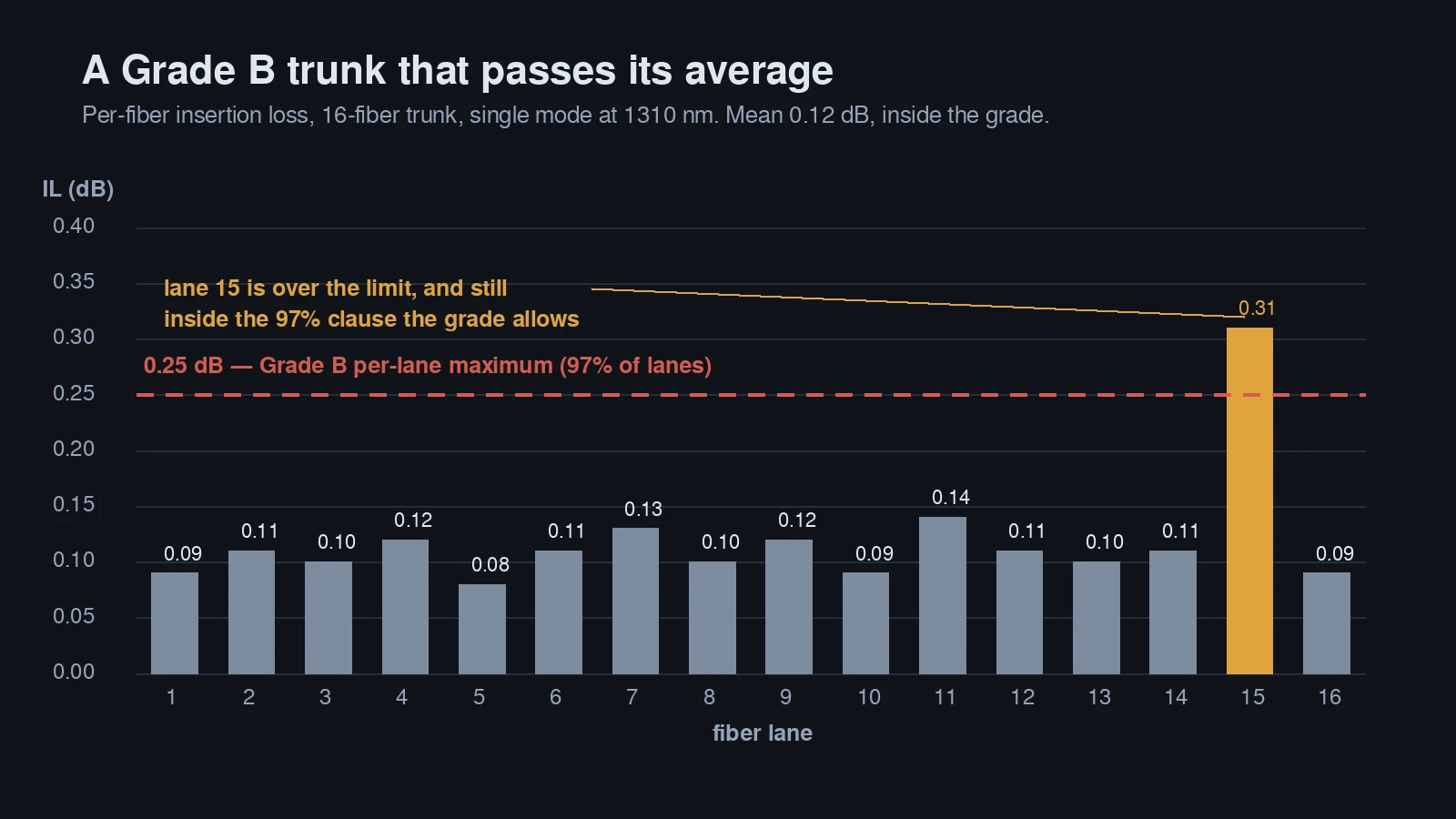
Illustrative values set to the Grade B mean and maximum: the average passes while one lane does not.
There is a second trap in the same table: how the loss was measured. IEC 61300-3-34 random mating is the field condition — any plug into any adapter. Each-to-each measurement pairs a specific plug with a specific adapter and reports the best case that pairing can produce. A report labelled "≤0.35 dB" is only comparable to another report if both used the same method. Ask which one; the number without the method is not a specification, it is a claim.
For a deeper treatment of how loss and reflection differ as failure modes, our guide to insertion loss vs return loss covers the measurement side.
MFD: the fiber spec that only shows up at the joints
Mode field diameter is the diameter of the light-carrying field, which is wider than the glass core and is the number that actually has to line up when two fibers meet. For G.652.D, ITU-T Recommendation G.652 (08/2024) specifies a nominal MFD of 8.6–9.2 µm at 1310 nm with a tolerance of ±0.4 µm; the older G.652.B window runs 8.6–9.5 µm with ±0.6 µm.
Read those two lines together and the problem appears. "G.652.D compliant" describes a window, not a value. Two reels from two suppliers can sit at 8.6 µm and 9.2 µm, both fully compliant, 0.6 µm apart. At a splice or a mated connector, mismatched mode fields do not overlap completely; the difference radiates into the cladding as loss, at exactly the location where you cannot re-terminate — the splice — or where you can only re-mate and hope.
At 100G this hid inside the budget. At 800G-DR8 the channel has 3 dB for 500 m of fiber, several mated pairs, and any splices. Fiber itself takes 0.2 dB of that. The remaining 2.8 dB is shared among joints, and a joint that is a tenth of a decibel worse than planned is no longer rounding error when there are five or six joints in one link.
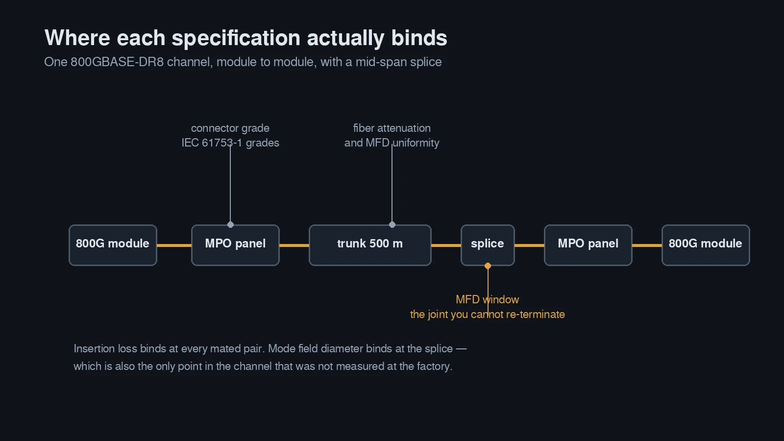
Insertion loss binds at every mated pair; MFD binds at the splice, which is the one point in the channel the factory never measured.
Bend-insensitive fiber makes the mismatch more likely, not less. G.657.A1 is designed for tight rack routing with a different refractive-index profile, and its permitted MFD range runs wider than G.652.D's — up to 9.5 µm against 9.2 µm. A dense AI row that runs a G.652.D trunk into a panel and then G.657.A1 pigtails into the optics has stacked the difference at the pigtail splice — the joint made in the field, at the end of a long shift, by a crew working to a turn-up date. Our comparison of G.652.D, G.657.A1 and G.657.A2 covers where each belongs.
What to do about it is unglamorous:
- Specify MFD as a nominal plus a window, not a fiber category. "9.2 ± 0.3 µm at 1310 nm" is a specification; "G.652.D" is a category.
- Keep one fiber source per link where you can, and one per trunk at minimum. Mixing suppliers mid-link is where mismatches get built in.
- Ask for MFD on the reel certificate, so the number follows the glass into the assembly.
- If you must mix G.652.D and G.657.A1, ask for both MFDs and cap the delta rather than assuming compliance implies compatibility.
Insertion loss: buy the maximum, measure every fiber
Supplier datasheets quote "typical" and "maximum" side by side, and buyers read the first column. The maximum is the only one that applies to the sample you receive. A typical value is a statement about a production population; your trunk is one draw from it.
A real specification looks like this, taken from our own insertion loss MPO trunk data: single-mode 12-fiber APC assemblies at ≤0.70 dB max standard grade or ≤0.35 dB max in the Elite grade, with return loss ≥60 dB; multimode 12-fiber PC at ≤0.50 dB standard or ≤0.35 dB Elite, return loss ≥20 dB. Both columns are measured on 100% of assemblies at 1310/1550 nm for single-mode and 850/1300 nm for multimode, and conformance is declared against GR-326 and GR-1435.
The gap between the two grades is not cosmetic. Take the 3 dB DR8 channel with four mated MPO pairs:
Mated-pair spec | Four pairs, worst case | 500 m of OS2 | Total | Margin against 3 dB |
|---|---|---|---|---|
0.70 dB max (standard) | 2.80 dB | 0.20 dB | 3.00 dB | none, before any splice |
0.50 dB max | 2.00 dB | 0.20 dB | 2.20 dB | 0.80 dB |
0.35 dB max (Elite) | 1.40 dB | 0.20 dB | 1.60 dB | 1.40 dB |
A standard-grade channel that adds a single field splice, or a slightly long patch run, is out of budget on paper before it is out of budget in the rack. That is the whole argument for low-loss assemblies at 800G: not because they are better engineering in the abstract, but because the arithmetic leaves nothing else.
Two other things belong in the same purchase order. Re-mating allowance: every move, add and change consumes part of a connector's durability budget, so ask for a limit on insertion-loss change after a defined number of matings, not just a first-mate number. Wavelengths: a single-mode report at 1310 nm only is a partial report if any part of your plant will carry 1550 nm traffic later.
Our walkthrough of how to build a loss budget for 400G links carries the same arithmetic further, including the difference between a link power budget and a channel insertion-loss allowance.
What a usable test report contains
At 800G an MPO test report is not paperwork attached to the shipment. It is the only instrument you have before installation, because after installation you are measuring a channel, not a part — and a channel measurement tells you the sum, not which lane is weak.
A report you can act on carries, per assembly, the six items below. The right-hand column is the tell: each row is also a way to fail.
Field | Why the buyer needs it | Reject signal |
|---|---|---|
Serial number and lot or reel traceability | Ties the paper to the bag in your hand | Serial on the report does not match the label |
Per-fiber insertion loss at every operating wavelength | A mean hides the lane that will trip the port | One "average IL" line for a 16-fiber assembly |
Per-fiber return loss, same structure | Reflection is a separate failure mode from loss | RL quoted as a single module-level figure |
End-face inspection per fiber, graded to IEC 61300-3-35 | A scratch is a future loss number | "Visual inspection passed", no grade, no per-fiber rows |
Measurement method and instrument | Random mated and each-to-each results are not comparable | Method unstated; no calibration date or uncertainty |
The raw data file | Lets you find the worst lane yourself | PDF summary only, worst lane absent or table truncated at fiber 12 |
Reports that fail the test look blandly professional: a stamp with no per-fiber rows, a sixteen-fiber assembly whose table stops at fiber 12, a PDF whose serial number does not match the bag. Each of these is a report about a population, not about the object in your hand, and at 800G the object in your hand is the thing that has to work.
What to look for on receipt is narrower than most QA checklists suggest: pick three serials at random, open the raw file, and find the worst lane. If the worst lane in the shipment is comfortably inside your channel allowance, the distribution is under control. If it is at or over, you have found the lane that will cost you a maintenance window, and you have found it before installation instead of after. Our note on per-shipment test reports covers how that documentation survives an audit.
Three lines to put in your RFQ
For fiber for AI data centers the argument compresses into three clauses. They cost nothing to write and they change what suppliers quote.
Requirement | What to write | Why it matters at 800G | How to verify |
|---|---|---|---|
MFD window | "Nominal MFD 9.2 ± 0.3 µm at 1310 nm; single fiber source per assembly; MFD stated on the reel certificate" | Joint mismatch is invisible in a connector grade | Reel certificate, plus a sample splice-loss check |
Per-fiber IL maximum | "All fibers measured at 1310/1550 nm (SM) or 850/1300 nm (MM); max per-fiber IL ≤ X dB, random mated; worst lane reported explicitly" | The tail decides; the mean does not | Read the per-fiber table, not the summary line |
Serialized raw data | "Raw per-fiber IL/RL data and end-face grade per serial number, delivered with the shipment" | Makes both clauses auditable after the fact | Pull three serials, match to the bag, read the worst lane |
The third clause is the one suppliers push back on, and it is the one that matters most: without it, the first two are promises. With it, they are specifications you can hold someone to.
An 800G DR8 channel, worked through
Five hundred meters of OS2, four MPO mated pairs (module to patch cord, patch cord to panel, panel to trunk, at each end), no splices. Fiber attenuation at 1310 nm is roughly 0.4 dB/km, so the glass costs about 0.2 dB. The connector figures below are the 12-fiber single-mode values from our own datasheet; a 24-fiber MPO is rated slightly higher at ≤0.75 dB standard grade, which makes the arithmetic tighter, not looser.
- Grade B worst case, 0.25 dB per pair: 1.0 dB of connections. Total 1.2 dB against a 3 dB allowance — 1.8 dB of margin.
- Standard grade, 0.70 dB per pair: 2.8 dB of connections. Total 3.0 dB. The channel is exactly at the limit with zero margin, and one field splice at 0.1–0.3 dB puts it over.
Now look at what the average would have told you. A supplier quoting "typical 0.18 dB per mated pair" describes a channel at 0.92 dB total — comfortable, and irrelevant, because the channel is judged lane by lane and pair by pair. The number that decides the turn-up is the sum of the four worst pairs on the weakest of sixteen lanes.
That is why the three clauses are not perfectionism. They are the difference between a link that commissions in an afternoon and a link that spends a week being re-patched while the rack waits.
Where this changes your 400G-to-800G plan
Migration planning is its own topic, and two of our guides cover it end to end: 400G to 800G data center cabling for fiber counts and OM4 versus OS2, and MPO polarity explained for the transmit-never-reaches-receive failure that no loss budget catches.
MFD and test data enter that plan at three specific points for fiber for AI data centers:
- Re-termination or splicing. The moment a link contains a splice, MFD mismatch becomes a line item. If the plant is factory-terminated end to end, the exposure is smaller but not zero.
- Supplier blending. A build that pulls trunks from one vendor and pigtails from another inherits the difference between their glass.
- Post-incident repair. A repaired link is a link with a new joint, and without per-fiber records you have no baseline to compare the repair against.
If the plant is already MPO-16, single-mode, and correctly graded, the migration is an optics swap and none of this is urgent. If any of those three is not true, the fiber specification is the project. If you are still buying pre-terminated trunks on price alone, what to check before you buy is the better starting point.
What to ask a supplier before you qualify them
Four questions separate suppliers who understand 800G from suppliers who have relabelled a 100G catalogue:
- Do you measure every fiber on every assembly, or a sample?
- What MFD window do you hold on the fiber you build with, and does it change between lots?
- Are your IL figures random mated or each-to-each?
- Can I have the raw file for one specific serial number, this week?
DYS Fiber Optic has built MPO/MTP assemblies since 2014 and runs 50,000 termination ends a day across standard and Elite grades, under TL 9000 certification held since 2025 — which is the floor for this conversation, not the answer to it. The answer is whether the per-fiber data arrives with a serial number attached and a worst lane you can read. Start with the data center fiber cabling guide for how the assemblies, loss budgets and migration path fit together.
Common questions at the specification stage
Is G.652.D good enough for 800G?
For 800GBASE-DR8 and its 500 m reach, yes — G.652.D is the standard single-mode choice, and G.657.A1 is the bend-insensitive variant for tight rack routing. The question is not the category but the MFD window inside it: two compliant G.652.D reels can be 0.6 µm apart, and that difference lands at the splice.
Does mode field diameter matter on multimode?
Not in the same way. Multimode loss is dominated by core alignment, core diameter and modal bandwidth, and the OM4/OM5 grades are specified around those. MFD mismatch is a single-mode joint effect, which is why it appears in DR8 and LR8 links and not in SR8 ones.
Can I mix connector grades inside one channel?
You can, and it is common during a phased build. But the channel is only as good as its worst pair, so the budget must be calculated with the worst grade in the path, not the best. Mixing a Grade B trunk with standard-grade patch cords gives you a standard-grade channel with a Grade B invoice.
What does "Elite" actually mean?
It is a supplier grade label, not an IEC grade. Anchor it to a number and a method — for example, ≤0.35 dB maximum per mated pair, measured random mated per IEC 61300-3-34 — and then require the per-fiber data that proves it. A label without a number and a method is marketing.