
Compliance
G652D vs G657A1 vs G657A2: ITU Fiber Standards and Bend-Insensitive Spec Choices
G652D vs G657A1 vs G657A2 is a question about the route, not about which grade is better. G.652.D offers the lowest attenuation and the least demanding bend behavior, and it stays the default for feeder and long-haul spans where the cable runs without tight loops. G.657.A1 keeps chromatic dispersion and polarization mode dispersion compatible with G.652.D while cutting the specified minimum bend radius from 30 mm to 10 mm, which covers most crowded cabinets, wall entries and drop terminations. G.657.A2 takes that further to 7.5 mm for high-density patch fields, narrow risers and any enclosure that forces a small coil. If the route is straight, stay on G.652.D; if it is tight, move up to A2; if you do not know yet, A1 is the safe middle.
Whatever you choose, write the grade down. Three suppliers quoting "single-mode" can deliver three different fibers, and on a site where a bend problem keeps reappearing, the grade is usually the variable nobody recorded. The G652D vs G657A2 and G657A1 vs G657A2 versions of the question are the same trade with a different endpoint, so the comparison below covers all three at once.
Quick Comparison: G652D vs G657A1 vs G657A2 at a Glance
G.652.D | G.657.A1 | G.657.A2 | |
|---|---|---|---|
ITU-T recommendation | G.652 (low-water-peak sub-category) | G.657, category A | G.657, category A |
Fiber design minimum bend radius | 30 mm | 10 mm | 7.5 mm |
How that radius is tested | 100 turns on a 30 mm radius, ≤0.1 dB at 1625 nm | 1 turn on a 10 mm radius, ≤0.75 dB at 1550 nm | 1 turn on a 7.5 mm radius, ≤0.5 dB at 1550 nm and ≤1.0 dB at 1625 nm |
Attenuation, typical published upper limits | ≤0.34 dB/km at 1310 nm, ≤0.20 dB/km at 1550 nm | ≤0.36 dB/km at 1310 nm, ≤0.22 dB/km at 1550 nm | ≤0.35 dB/km at 1310 nm, ≤0.21 dB/km at 1550 nm |
Dispersion and PMD compliance with G.652.D | The reference | Complies | Complies |
Mode field diameter at 1310 nm | ≈9.2 µm (typical of the installed base) | Kept compatible with G.652.D | Kept compatible with G.652.D |
Typical deployment role | Feeder, metro, long-haul, any straight route | Distribution, drop entries, general access routing | Patch fields, risers, dense indoor routing, cable assemblies |
Read that table as a set of design values, not as installation limits. The last column of any fiber datasheet describes the glass under a defined test; the cable you pull, the tray you coil it into and the tension you apply each have their own limit, and they are set by the cable and hardware standards rather than by the fiber recommendation.
What the ITU-T Standards Actually Specify
Two recommendations cover everything in this comparison. The ITU-T G.652 recommendation defines the standard single-mode fiber family and its low-water-peak sub-categories, including G.652.D, which extends usable transmission from the O-band through to the L-band by suppressing the hydroxyl absorption peak near 1383 nm. The ITU-T G.657 recommendation defines bending-loss insensitive single-mode fiber and cable, and it splits into two categories rather than one ladder:
- Category A must comply with G.652.D's chromatic dispersion and polarization mode dispersion requirements. G.657.A1 and G.657.A2 both sit here, which is why they can be deployed into an existing G.652.D network without reworking the link budget.
- Category B need not meet all of those requirements. B-class fibers are system-compatible with category A and with G.652.D in access networks, but "compatible in practice" is not the same statement as "meets the same dispersion specification".
If your design rule is simply "use the smallest bend radius available", category B3 at 5 mm looks like the top of the range. It is not a superset of A2. It is a different trade, made for concealed and very short-reach indoor routing, and it comes with looser dispersion and PMD guarantees than the A grades.
One version detail catches people out. The 08/2024 edition of G.657 merges the former B2 sub-category into A2. A bill of materials written in 2019 can therefore specify "G.657.B2" for a role that the current edition assigns to A2. If that line item is still in your template, the correct move is not to substitute silently: ask the supplier which edition the delivered fiber is designed against, and get the replacement reference agreed in writing before the reel ships.
If there is any doubt about which family a cable belongs to, single-mode versus multimode fiber is the wider comparison; the three grades below are all single-mode.
Bend Radius: Why 30 mm, 10 mm and 7.5 mm Are Not Comparable Numbers
Put the three numbers in one column and the eye reads a ranking. The specifications do not support one, because the three tests differ on radius, on turn count and on wavelength at the same time.
The G.652.D figure is a bend-loss requirement under many turns: 100 turns wound on a 30 mm radius, with the added attenuation kept to 0.1 dB or less measured at 1625 nm. One hundred turns is a stress test for a whole coil. The G.657.A2 figure is a single-turn requirement at a much tighter radius: one turn on 7.5 mm, with added loss allowed up to 0.5 dB at 1550 nm and 1.0 dB at 1625 nm. That is a different question asked of the fiber — "what happens in the one tight loop an installer creates?" — and it is deliberately allowed a much larger loss allowance.
So when a supplier table lists 30 mm, 10 mm and 7.5 mm side by side, the honest reading is not "7.5 mm is four times better than 30 mm". It is:
- G.652.D is characterized for wound coils at a comparatively generous radius.
- G.657.A1 and A2 are characterized for individual tight turns, at wavelengths that matter in access networks.
- The reason A1 and A2 exist is not that they are stronger in the abstract; it is that the added loss in a standard G.652.D fiber climbs steeply as the radius tightens, and access routing pushes cables into exactly that range. The G.657 standard states the problem directly — as FOA's guide to bend-insensitive fiber quotes it, G.652 fibers deployed at a 15 mm radius "generally can have macrobending losses of several dB per 10 turns at 1625 nm". Several decibels is past the tolerance of any link, and that is at 15 mm rather than 7.5 mm.
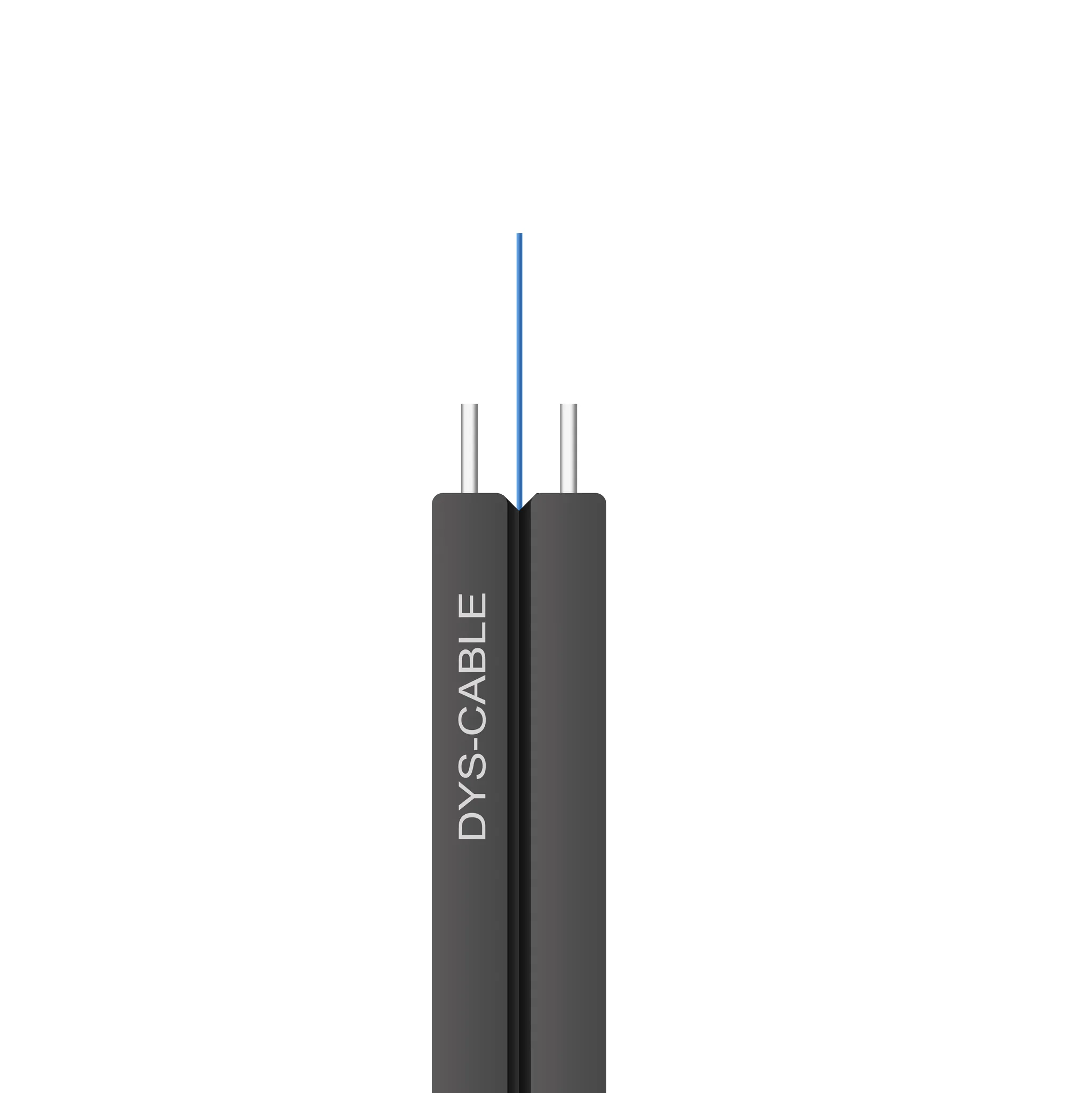
The flat drop cable above is where this argument is settled in practice. Two strength members sit either side of a single coated fiber inside a low-profile jacket, and the whole assembly is stapled, clipped and coiled into a subscriber wall box with very little slack. There is no room to enforce a 30 mm radius, which is why drop constructions are normally specified with an A-grade fiber — not because A-grade fiber is new, but because the physical shape of the cable leaves no alternative.
Practical rule: treat the 30 / 10 / 7.5 mm numbers as pointers to which grade was designed for your route, then take the actual limit from the cable and hardware datasheets.
Attenuation, Chromatic Dispersion and PMD: Where G.652.D Still Leads
Bend performance is not free. The A grades buy their tighter radius with a small penalty, and the size of that penalty depends entirely on how far the signal has to travel.
Published specification tables for the three grades typically quote attenuation upper limits around 0.34 dB/km for G.652.D against roughly 0.36 dB/km for G.657.A1 and 0.35 dB/km for G.657.A2 in the 1310 nm window, and about 0.20 dB/km against 0.22 and 0.21 dB/km at 1550 nm. The exact figures vary by manufacturer and by fiber count, so treat them as the shape of the difference rather than as constants.
What matters is the distance over which that difference accumulates:
- A 0.01 dB/km gap becomes roughly 1 dB over a 100 km span.
- A 0.02 dB/km gap becomes roughly 2 dB over the same distance.
Against a typical access link of a kilometer or two, that is noise — a fraction of a decibel, well inside the margin any competent design already carries. Against an amplified long-haul span, 1 to 2 dB is worth arguing about with your transmission engineer. That asymmetry is the whole reason the three grades coexist: the penalty is real but it is only material where the route is long, and long routes are exactly the ones that are not forced into tight bends.
The dispersion picture is more binary. G.652.D is characterized with a zero-dispersion wavelength in the 1300–1324 nm region and chromatic dispersion of roughly 17 ps/(nm·km) at 1550 nm, which is why long 1550 nm links built on it need dispersion compensation or coherent transmission. Categories A1 and A2 inherit G.652.D's dispersion and PMD compliance, so mixing them into a G.652.D network does not change the dispersion map — a point worth having in writing when a design reviewer asks whether a mix is safe. Category B is where that guarantee lapses.
Splicing G.657 onto G.652.D: Mode-Field Mismatch and Your OTDR Trace
"Compatible" gets used as if it meant "identical". It does not, and the gap shows up at the splice.
Bend-insensitive design changes the refractive index profile, and one of the ways it can buy bend tolerance is by shrinking the mode field diameter. That is why the G.657 specification carries tighter mode field boundaries than the older G.652 text. FOA's bend-insensitive fiber reference reproduces the fiber makers' own account of the change: the G.657 specification was modified to place more stringent boundaries on mode field diameter specifically to assure compatibility with standard G.652 fiber, and ITU has studied the full transmission parameter set for G.657.A1 and A2 and stated that the products are fully compatible. Compatibility is therefore a design commitment rather than an accident — but it is not identity. The more bend-insensitive products on the market, particularly the tighter A2 and B3 designs, trend toward a smaller mode field, and a mixed splice behaves a little differently from a like-for-like one as a result. FOA's loss-budget reference gives the planning figures to start from, and it also draws a line that gets crossed constantly on site: single-mode fusion splices typically come in under 0.05 dB, while the familiar 0.3 dB average belongs to multimode mechanical splicing. Quoting the multimode number at a single-mode mixed joint is a reliable way to reject a splice that was never a problem.
Three things make mixed splicing predictable:
- Select the splicer's dissimilar-fiber program. Whether a given splicer's automatic mode handles a G.652.D-to-G.657 pair correctly is model-specific. Check the manufacturer's program list instead of assuming the default is safe, and record the program used in the installation records.
- Specify both sides of the joint. A pigtail is a fiber choice as much as a drop cable is. "Single-mode pigtail" on a purchase order leaves the grade, the connector polish and the buffer construction open to substitution.
- Measure the splice in both directions. This is the step most often skipped, and it is the one that decides whether a mixed splice is genuinely bad. A one-way OTDR trace can misread splice loss when the two joined fibers have different backscatter characteristics: the event can look like a gain in one direction and an exaggerated loss in the other. FOA's bend-insensitive fiber reference makes the mechanism explicit — reducing the mode field diameter for better bend performance creates mismatch loss at splices and connections and produces one-way OTDR "gainers" that call for bidirectional testing — and Corning application note AN3060 sets out the bidirectional averaging that removes most of the bias.
For a mixed-fiber qualification package, agree the test plan before volume installation: identify the same splice event on both traces and keep the original files, keep the test conditions comparable and recorded (wavelength, pulse width, instrument settings), judge the event against the project's own splice criterion, then check end-to-end loss against the link budget and investigate anything that does not reconcile. Where only one end is reachable, say so in the records rather than presenting a one-way estimate as a bidirectional result. The field testing and acceptance procedure for fiber links covers the wider handover set, and if the choice is still open between joining methods, fusion splicing, mechanical splicing and connectorization compared puts the three side by side.
Fiber Grade vs Finished Cable: Which Bend Limit Actually Applies
The 7.5 mm figure belongs to the glass. It is not the number to give an installation crew.
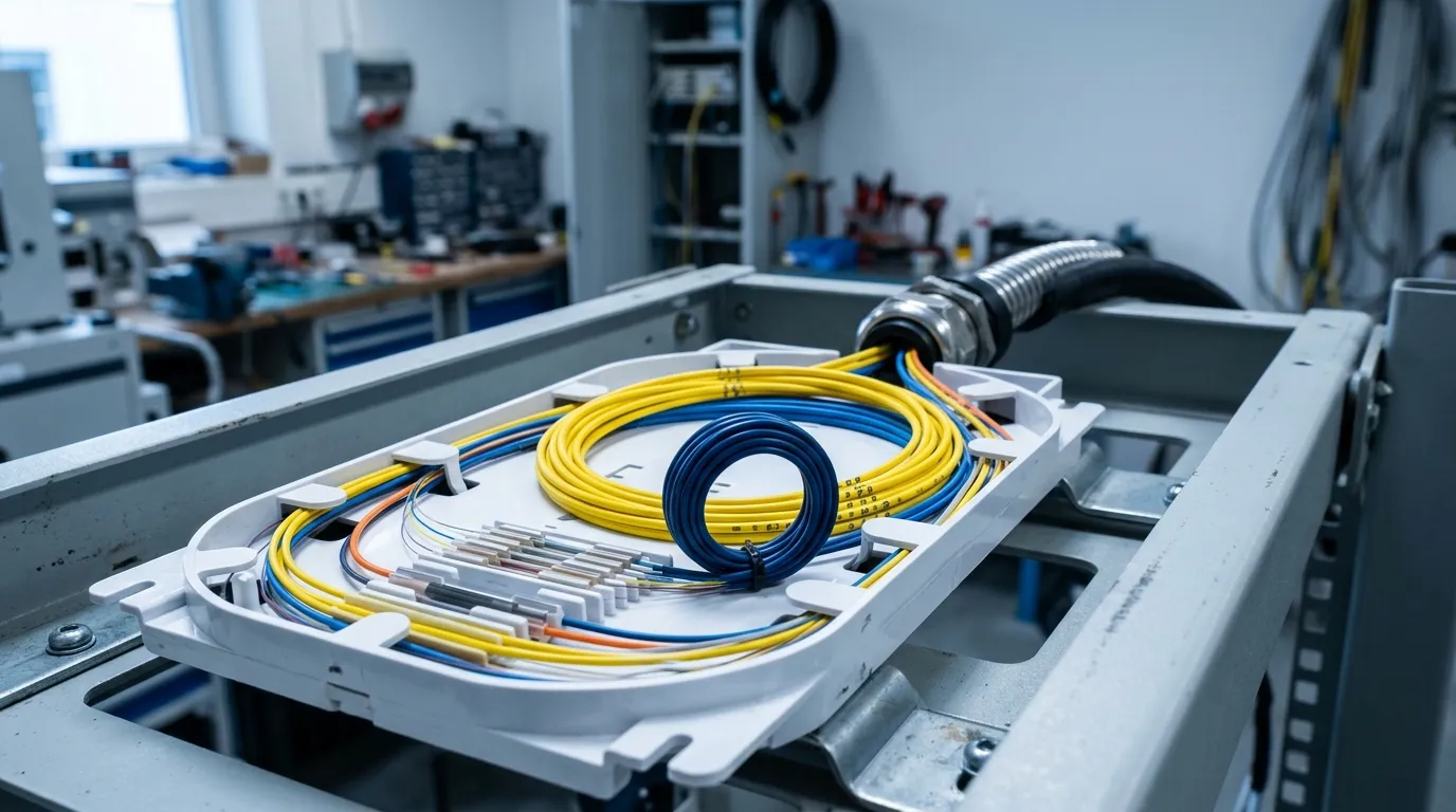
A finished cable is glass plus buffer, strength members, jacket and possibly armor, and its permitted bend radius is expressed as a multiple of the cable's own diameter — a different quantity with a different value. Connector boots, splice trays, wall boxes and patch panels each impose their own routing limit, and the tightest of them governs. This is why a site can specify A-grade fiber, still trip bend-loss alarms, and find on inspection that an installer closed a tray on a loop the hardware never allowed. The bend radius rules for installed fiber cable article works through those cable-level and hardware-level limits.
Two consequences follow. First, when a bend problem appears, establish which layer is at fault before changing the fiber grade — a grade upgrade does not fix an enclosure that shapes the wrong loop. Second, the routing limit of hardware is a specification you can buy against: tray internal radius, the entry angle at the adapter and the slack allowance behind a connector all belong in the enclosure datasheet, and they can be compared across offers.
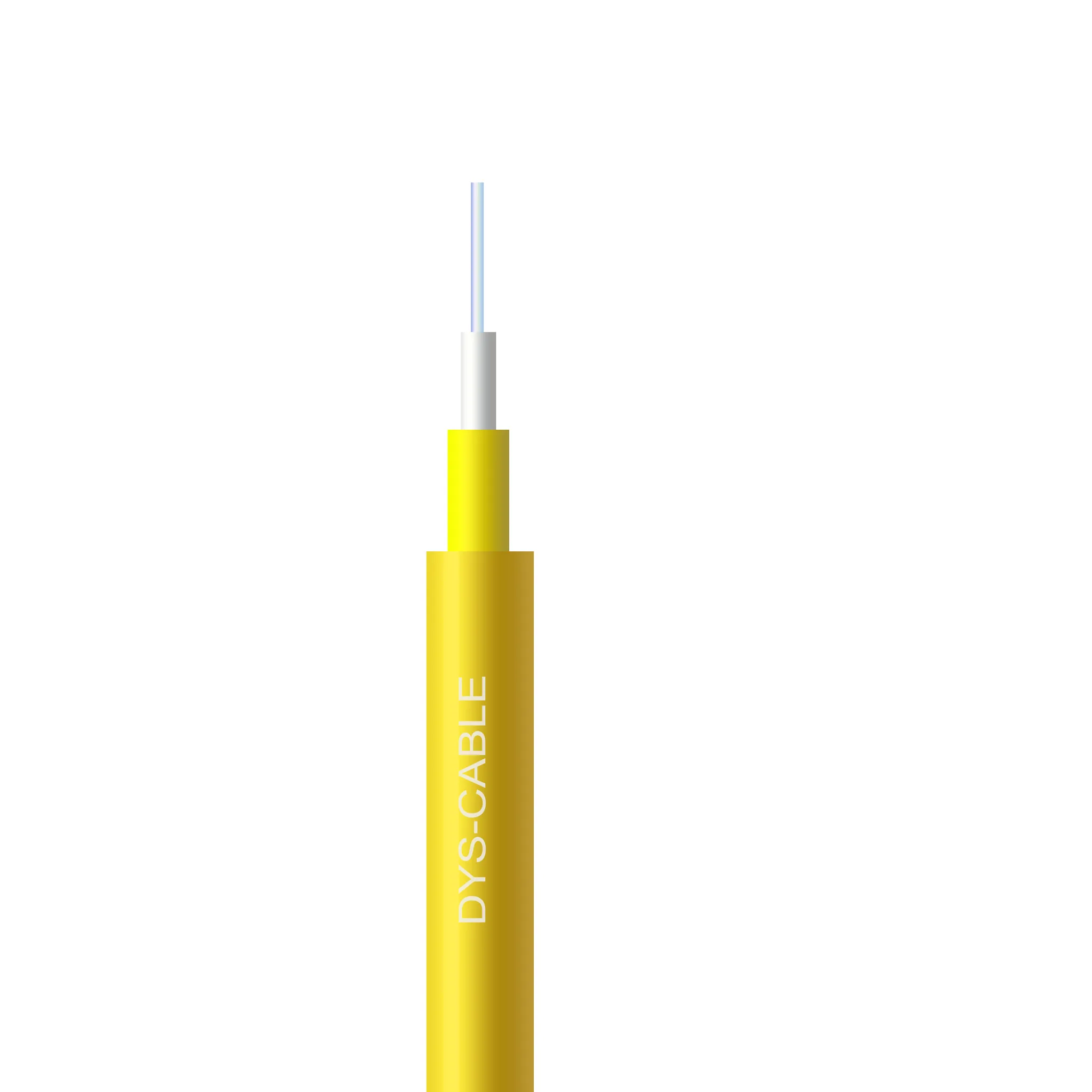
Indoor simplex cable like this 2.0 mm construction is the case the point is usually made about. It is soft, it is handled by people rather than by cable-winches, and it is the component most likely to be dressed into a radius nobody designed. The fiber inside may well be an A grade; the cable still has a minimum bend radius of its own, and it is that limit — not the glass figure — that belongs in the method statement.
Where Each Grade Belongs in an FTTH or Data-Center Build
Segment by segment, the shortlist usually comes out like this.
Project situation | Grade to shortlist | Evidence to collect before approval |
|---|---|---|
Existing G.652.D feeder or distribution network | Keep the approved specification; review an alternative only against a documented need | Existing fiber identity, cable construction, network requirements |
New distribution run through crowded ducts | G.657.A1 | Finished-cable bend limits for the routing and pulling method |
Drop to the subscriber, terminated in a small wall box | G.657.A1 or A2 | Entry dimensions, termination plan, cable-construction limits |
Indoor riser, MDU vertical, dense patch field | G.657.A2 | Adapter format, boot clearance, tray internal radius |
Very confined concealed routing, short reach | G.657.B3, if the design rule allows category B | Approved application, complete product limits, connection qualification |
New build on a straight, long feeder route | G.652.D | Link budget with the dispersion and PMD assumptions recorded |
Data-center cabling sits at the dense end of the same logic. Trunks and harnesses are routed in trays where a 30 mm radius is a luxury, and patch fields are built to be re-dressed by hand, so A-grade patch cords are common. Because A1 and A2 remain compliant with G.652.D dispersion and PMD, moving to them does not force a redesign of the link budget — which is the practical reason the change is usually safe where the length is short.
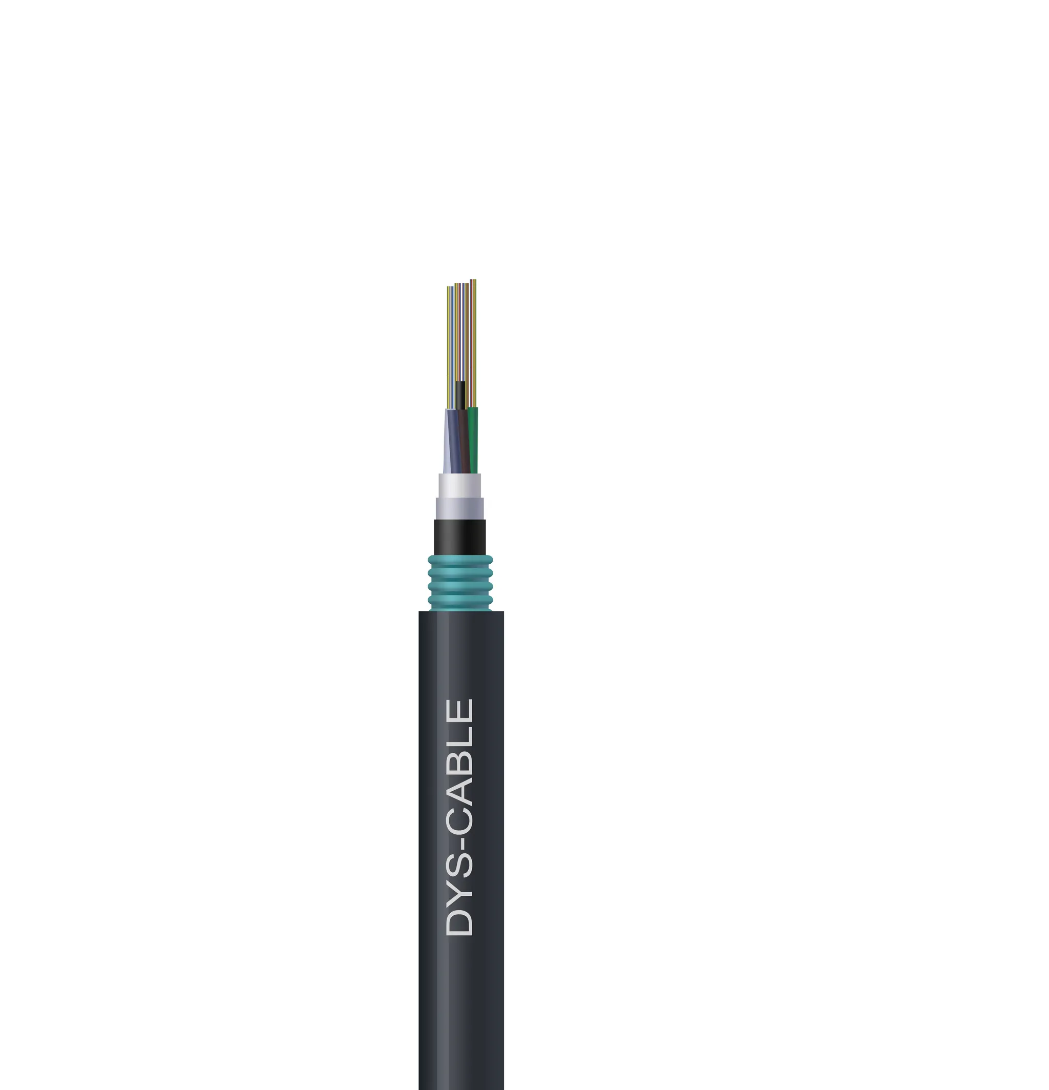
Outdoor armored constructions such as the one above show where the opposite logic holds. The physical constraint on a buried or duct feeder is not a tight bend — it is crush, moisture and tensile load, handled by loose tubes, water-blocking yarn and corrugated steel tape. Routes like this can be laid to generous radii, so paying for bend-insensitive glass buys nothing the route needs, and the lower attenuation of G.652.D is worth more. For the subscriber end of the same network, the FTTH drop cable selection guide takes the drop constructions further, and the FTTH drop cable range shows how flat, self-support and round drop types map onto them.
How to Specify and Verify the Grade You Ordered
Everything above collapses into a handful of line items, and none of them is expensive.
Write the grade, not the category. "Single-mode fiber" describes a family. The purchase order should state the ITU-T letter and sub-category — G.657.A2 — together with the cable construction, the assembly specification and the standard edition the design follows. Where a legacy bill of materials still names a withdrawn sub-category, resolve it against the current edition rather than accepting an unstated equivalent.
Ask for the grade in the test data, not only in the drawing. A datasheet states what the fiber is designed for. The reel, the drum label, the factory test report and the delivered cable jacket marking state what was actually shipped. Requesting that the grade appears in the shipment documentation is what turns a fiber choice into something an incoming inspector can verify. Our own production runs every drum through pre-shipment testing under an ISO 9001 and TL 9000 quality system, with in-house tooling for the molded and assembled parts of the chain — which is one reason we can state grade and construction together on the certificate for an order rather than only on the marketing sheet.
Agree the substitution rule in advance. Any change to fiber grade, cable construction or assembly specification should be identified by the supplier before shipment and approved against the same project requirements. An "equivalent" that arrives without a document is not a specification, it is a decision someone else made.
Separate the civil works question from the compliance question. These are two different layers, and conflating them is a common source of delay. The fiber grade is a glass-level choice; the marks the market demands — a UL listing for the United States, CPR classes in the European Union, Anatel approval in Brazil, TL 9000 for telecom quality systems — are specified and verified on the finished cable and the manufacturer's system, not on the glass inside it. A cable built around G.657.A2 is not automatically compliant with any of them, and a CPR class tells you nothing about bend performance. The CPR fire-rating classes for fiber cable in the EU sets out the fire-rating side, and the fiber optic certifications and compliance guide covers how the regional schemes fit together for a procurement package.
Qualify with a trial, then freeze the specification. For any mixed-fiber route, install a representative sample, splice it, and measure it with the method you intend to use at acceptance — including bidirectional OTDR on the mixed joints. When the trial passes, freeze the fiber references and the acceptance method in the project documents, and hold later shipments against them.
Bottom Line: Choosing Between G.652.D, G.657.A1 and G.657.A2
- Straight, long, generous radii → G.652.D. Lowest attenuation, the reference dispersion and PMD, and the simplest construction to buy for a route that does not need anything else.
- Access routing with ordinary cabinet and entry bends → G.657.A1. G.652.D-compatible dispersion and PMD, a 10 mm design radius, and no link-budget redesign.
- Risers, dense patch fields, assemblies and tight indoor routing → G.657.A2. The 7.5 mm design radius is what high-density hardware assumes.
- Concealed, very short reach and the design rule permits category B → G.657.B3, with the looser dispersion and PMD guarantees treated as a deliberate trade.
- Not sure yet → specify A1, measure the real route, and move to A2 only where the hardware forces it. Then write the grade down, ask for it in the test data, and hold the acceptance method fixed.
The three grades are not a ladder to climb. They are three points on a trade between bend tolerance and attenuation headroom, and the route you are building picks the point for you. If you are assembling a procurement package for a multi-region rollout and want the fiber grade, the cable construction and the certification evidence to line up on one document set, send us the route and the hardware list and our engineers will work the specification through with you.