
Compliance
Fiber Optic Test Reports: What to Demand Per Shipment
The cables you bought will spend twenty years underground or overhead, and you will never see them again. Every claim about their performance arrives as a document. That document is usually a PDF with a table of numbers, sometimes an Excel export, occasionally a photograph of a printout, and it is the only evidence you have that the insertion loss you paid for is the insertion loss you received.
Most of these documents cannot be audited. Not because the numbers are wrong, but because nothing on the page tells you where they came from — no method, no instrument serial number, no calibration date, no limit to compare against. You end up trusting the format instead of the content, and a well-formatted report is exactly as easy to produce as a real one.
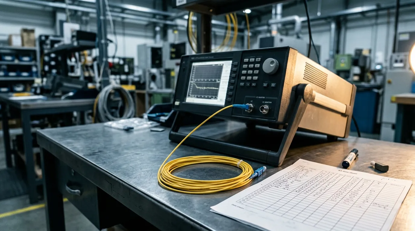
A per-shipment fiber optic test report is the document a manufacturer issues with a specific delivery, recording the measured insertion loss and return loss of each fiber, port or assembly in that shipment alongside the method and instruments that produced the numbers. It is not a certificate, it does not expire, and it is not transferable to the next shipment.
A test report is not a certificate — and that distinction decides what you can claim
Three documents travel with fiber orders and buyers routinely accept one when they needed another.
A product certification — UL for the US jacket ratings, CPR for the EU construction-products classes, Anatel for Brazil, TL 9000 for the telecom quality system — is an approval of a design or a system, granted once and audited periodically. It says a class of product may be sold or a plant is run a certain way. It says nothing about what came off the line last Tuesday. If you want to see how these fit together, the fiber optic certifications and compliance hub maps the schemes and what each one actually proves.
A certificate of conformity is a one-page statement: this delivery meets the specification referenced in your order. It is a legal declaration, not a measurement. Useful when a customs broker or a project QA file needs it; useless when you want to know whether port 37 of trunk 12 is passing.
A test report is the only one of the three that carries per-unit measurements. And the whole point of a per-shipment report is that it is bounded — one lot number, one set of work orders, one fiber count, one test date, one lab.
The practical consequence: when a supplier answers a data request with a folder of certificates, the data request has not been answered. That happens constantly, and it is not always evasion — many sales teams genuinely do not know which document their own factory issues.
The standards behind the numbers are public and checkable, which is what makes the numbers auditable. The FOA's standards reference lists the fiber-optic test standards by family if you want to see how the documents are structured before you ask for one.
What a per-shipment fiber optic test report has to contain
The list below is a working specification for a fiber optic cable test report, not a wish list. The left column is what makes a report binding; the right column is what lets you use it.
Field | Why it decides whether you can accept |
|---|---|
Purchase order and work order number | Ties the document to the delivery you are paying for. Without it, a report from last quarter looks identical. |
Product description, part number, connector type, polish | Establishes what was tested. A report for "patch cord" with no part number cannot be checked against the spec you bought. |
Cable lot and assembly serial range | The traceability anchor. If one reel fails a year later in the field, this is the line that finds the other reels from the same extrusion. |
Quantity tested versus quantity shipped | Turns "100% tested" from a phrase into a number you can check by counting rows. |
Wavelengths tested | Insertion loss is wavelength-dependent. 1310 and 1550 nm for single-mode, 850 and 1300 nm for multimode, and what your order needs may be narrower. |
Per-unit insertion loss (dB) | The primary acceptance number, one row per fiber, port or assembly. |
Per-unit return loss (dB) | The second acceptance number, and the one most often missing entirely. |
Limit applied and pass/fail result | A number without a limit is an observation, not a judgment. The limit class matters — see the next sections. |
Test method and standard reference | IEC 61300-3-4 for attenuation, IEC 61300-3-6 for return loss, plus the internal work instruction. This is what makes the number reproducible. |
Instrument identification and calibration due date | The report is only as good as the meter. An expired calibration turns a pass into an open question. |
Inspector name or ID and approval signature | Accountability. A report with no named signer has no owner. |
Date of test | Separate from ship date, and the two should be sensibly close. |
End-face inspection result | Cleanliness and geometry, usually against IEC 61300-3-35. Supplementary to the optical numbers, not a replacement for them. |
Raw data availability (CSV or trace files) | The escape hatch. If you ever need to re-plot or re-judge, you need the source file, not a summary table. |
Two fields are worth asking for and almost never volunteered: the fiber grade and the sampling plan, if the supplier is not testing every unit.
The grade matters because the names are not a quality ladder. G.657.A1 and A2 are subsets of G.652.D — the framing used in the ITU-T G.657 recommendation itself — with the same transmission and interconnection properties; what changes is the minimum macro-bend radius, which is the number that decides whether a tight tray or a bend-heavy route is still inside spec. The B grades are a different compromise and are not required to match G.652.D on chromatic dispersion and PMD. A report that says only "single-mode" has hidden the one field that tells you which of these you received.
The sampling plan changes how much of the shipment the document actually covers, so ask for it before you release payment on a large order.
The instinct for this kind of verification is the same one behind checking a supplier's UL listing: the document is a claim, and a claim has an owner, a scope and a date you can look up.
Which number came from which method
An insertion loss figure and a return loss figure are produced by different instruments under different standards, and a report that treats them as one category is a report written by someone who did not run the test.
Insertion loss is measured with a light source and a power meter — the pair usually called an OLTS when the two are combined. IEC 61300-3-4 is the standard that defines the attenuation measurement methods for optical components; the setup the industry actually runs against it, a calibrated 0 dB reference built from reference cords, is documented by the FOA's testing reference, including the one-, two- and three-reference-cord variants and the note that TIA-568 originally specified the one-cable method. That history is why two labs can both be "following the standard" and still produce numbers that differ by a few tenths of a dB.
For cable rather than assemblies, the same measurement often appears in a different form. Attenuation along a reel is frequently evidenced by an OTDR trace with an event table, where the trace shows splice and connector events along the length and the event table summarises their loss and reflectance; the per-fiber loss table is then derived from, or cross-checked against, those files. If your order is cable rather than patch cords, ask whether the trace files ship with the report — a summary table alone cannot show a localised event in the middle of a span.
Return loss is a ratio: incident power to reflected power, expressed in dB, and defined that way by IEC 61300-3-6. Two consequences for anyone reading a report. First, a return loss value without a stated wavelength is not a measurement — reflectance changes with wavelength and with the launch condition. Second, RL is a minimum specification (≥50 dB, ≥60 dB), and higher is better, which is the opposite direction from insertion loss. Reports that print both columns under one "result" header invite the reader to misread one of them.
End-face condition is a third, separate measurement. IEC 61300-3-35 defines the visual inspection and classification of debris, scratches and defects on connector end faces, and it is explicit about its own limits: visual inspection is in addition to, and does not replace, measurement of attenuation and return loss, and a connector cannot be rejected on a visual failure alone — optical performance determines fitness for use. A supplier who offers "100% end-face inspected" as proof of quality has answered a different question than the one you asked.
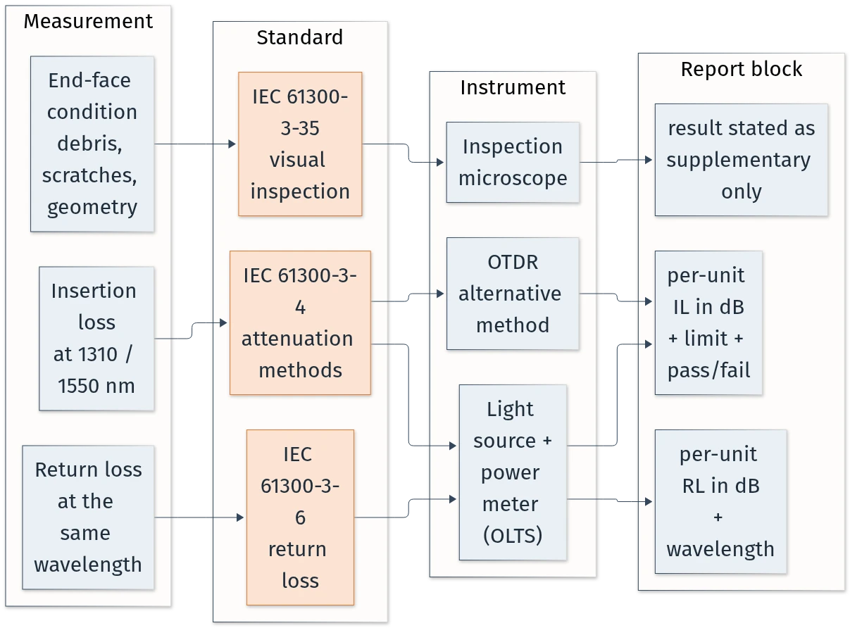
Three measurements, three standards, three instruments — and three distinct blocks on a report that can be audited separately.
Calibration closes the loop. The FOA's reference notes that meters calibrated against national primary standards carry a calibration uncertainty of roughly ±5% of optical power, and that instruments are normally recalibrated annually. That ±5% is not 5% of the dB reading: converted, it is worth about ±0.21 dB before the repeatability of the mating itself is counted. Against a 0.30 dB acceptance limit, that means a reported 0.29 dB and a reported 0.31 dB are not distinguishable — which is why the third decimal on a report is noise rather than precision. Labs operating under ISO/IEC 17025 accreditation — the framework whose mutual recognition is documented by ILAC — are required to state their uncertainty and keep the calibration chain visible, so a report from an accredited lab should say what that uncertainty is. When you ask for the calibration certificate, you are asking whether the report's decimal places are real.
Reading the pass/fail line by product class
The same words — "insertion loss, max 0.35 dB" — mean completely different things depending on what is being measured, and this is where most purchase orders go wrong: they inherit a limit from a different product family.
Take three items that ship in the same crate on a data-center order:
- A duplex patch cord is judged connector by connector, and the polish decides the number. DYS's own LC datasheet reads ≤0.30 dB insertion loss with ≥50 dB return loss for UPC, and ≤0.20 dB with ≥60 dB for APC — so the 0.20 dB figure is an APC result, not a separate "low-loss tier". Those are per-assembly figures; if your PO is written per mated pair, say so, because the two conventions differ by one connector.
- An MPO/MTP trunk is judged per mated MPO pair, and the grade is a commercial choice. A standard 12-fiber single-mode APC trunk is commonly specified at ≤0.70 dB insertion loss with ≥60 dB return loss, while the same trunk in a low-loss "elite" grade is ≤0.35 dB. Multimode 12-fiber trunks are quoted at ≤0.50 dB with ≥20 dB return loss. Same connector count, two very different acceptance lines. The report should also record which polarity was built — A, B or C — and the keying at each end, because a trunk that passes insertion loss with the wrong wiring is still unusable; MPO polarity explained covers the conventions.
- A PLC splitter is not a connector problem at all. A 1×8 splitter spends about 9.0 dB on the split ratio alone — that is 10·log₁₀(8) — and is then specified at a maximum insertion loss that includes the excess loss. Published limits differ by family: a 1×8 with LC/SC outputs is quoted at ≤10.3 dB in the accessories range, while the data-centre MPO-output range is quoted at ≤10.9 dB for LC/SC and ~11.3 dB for MPO. Return loss is ≥50 dB UPC and ≥60 dB APC on the accessories LC/SC range, and ≥50 dB UPC / ≥55 dB APC on the data-centre range. One caution on splitter datasheets: ≥55 dB appears there as more than one thing — on the data-centre table it is both the directivity figure and the return-loss figure for connectorised APC parts, so read the row it sits in rather than guessing the parameter from the number. A report showing 1.2 dB for a 1×8 splitter is not excellent, it is a different device or a transcription error.
Set side by side, the acceptance lines look like this — and none of these numbers is transferable to another row:
Product class | Judged per | Typical insertion loss limit | Typical return loss limit | Test wavelengths |
|---|---|---|---|---|
Duplex LC patch cord | connector / assembly | ≤0.30 dB UPC / ≤0.20 dB APC | ≥50 dB UPC / ≥60 dB APC | 1310 / 1550 nm, single-mode |
MPO/MTP trunk, standard grade | mated MPO pair | ≤0.70 dB (12F SM APC), ≤0.50 dB (12F MM) | ≥60 dB SM / ≥20 dB MM | SM 1310/1550, MM 850/1300 |
MPO/MTP trunk, low-loss grade | mated MPO pair | ≤0.35 dB | ≥60 dB SM / ≥20 dB MM | SM 1310/1550, MM 850/1300 |
PLC splitter, 1×8 | whole device, all outputs | ≤10.3 dB (LC/SC accessories range), ≤10.9 dB (LC/SC data-centre range), ~11.3 dB (MPO outputs) | ≥50 UPC / ≥60 APC (accessories LC/SC); ≥50 UPC / ≥55 APC (data-centre); directivity ≥55 on both | 1310 / 1490 / 1550 nm |
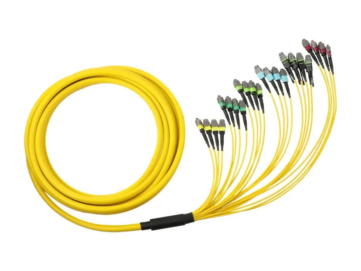
An MPO/MTP-to-LC fanout from the trunk product family: twelve LC channels off a single MPO end, each carrying its own insertion loss and return loss row in the shipment report.
Two rules follow. First, the report must name the limit class it was judged against — standard versus low-loss, UPC versus APC, and the wavelength set. A number of 0.5 dB per port passes a standard MPO trunk and fails an elite one; without the class, the pass/fail column is unreadable. Second, the wavelength set must match the product: single-mode trunks are tested at 1310 and 1550 nm, multimode at 850 and 1300 nm, splitters at 1310, 1490 and 1550 nm. A single-mode assembly reported at 850 nm was measured on the wrong instrument, and no amount of internal consistency fixes that.
If the IL and RL direction still feels inverted, insertion loss versus return loss walks through both definitions with the formulas and typical connector limits; the short version is that one is a budget you spend and the other is a floor you must stay above.
Five arithmetic checks that expose a report you cannot trust
You do not need a test bench to audit a report. You need arithmetic and a suspicious disposition, applied in this order.
1. Identical values across channels. Real measurements scatter. If a 24-fiber trunk reports 0.21 dB on all twenty-four channels, one of two things happened: the row was filled from a single measurement, or the file was templated. Either way you are looking at data that was not measured per port. A handful of repeats is normal; a whole table at one value is not.
2. A return loss value with no wavelength, or an insertion loss value with no test condition. Both are method-dependent numbers. If the column header says only "RL (dB)", ask which wavelength and which reference method produced it — the answer is often "we don't record that", which tells you how the rest of the table was built.
3. Values finer than the system can resolve. Insertion loss reported to 0.001 dB, or a flat 0.00 dB on a mated pair, is a claim about measurement precision that a power-meter setup cannot support. Two connectors mated once will not produce zero loss; the repeatability of the mating itself is larger than that.
4. Coverage that does not match the shipment. Divide the number of measured rows by the quantity shipped. A 288-fiber lot reported with 24 measured rows is a sample, not a full test, whatever the cover page says. The inverse check is also worth running: a "100% tested" claim on a shipment of 40 reels should produce per-fiber attenuation for every fiber on every reel, which is a lot of rows — if the report is two pages, the claim and the evidence do not match.
5. Calibration and instrument identity. Every reported number should point at an instrument with a calibration date that precedes the test date and a due date that follows it. Watch two things. First, whether the calibration certificate actually covers the wavelengths on the report — quad sources covering 850, 1300, 1310 and 1550 nm are standard, so one instrument ID across two bands is normal; what is not normal is a single-mode part reported at 850 nm, or a certificate scoped to one band. Second, a calibration date comfortably older than the report with no due date shown at all.
Run these five and you will catch the difference between a report that was generated and a report that was written. The same disposition, applied to the plant rather than the paperwork, is what a factory audit for fiber optic cable is for: watching the test station produce a number you can then find in the report.
"100% tested" versus sampling: what the claim can legitimately mean
"100% tested" is one of the most repeated and least defined phrases in fiber procurement, and it is not dishonest — it is under-specified.
For cable, a defensible reading is that attenuation is measured on every fiber of every reel. That is achievable inline and it is what the phrase should mean: no fiber ships unmeasured.
For assemblies, the equivalent claim is that every port of every assembly was measured for insertion loss and return loss after termination. Also achievable, and the number of rows in the report should equal ports × assemblies.
For qualification and reliability testing — environmental cycling, tensile and torsion, waterproofing to IPX8, GR-326-style connector reliability — "100%" is the wrong frame entirely. Those are design and process qualifications performed on samples, repeated on a schedule, not on every shipment. A report that presents a type-test certificate as if it were per-shipment data is conflating two documents again.
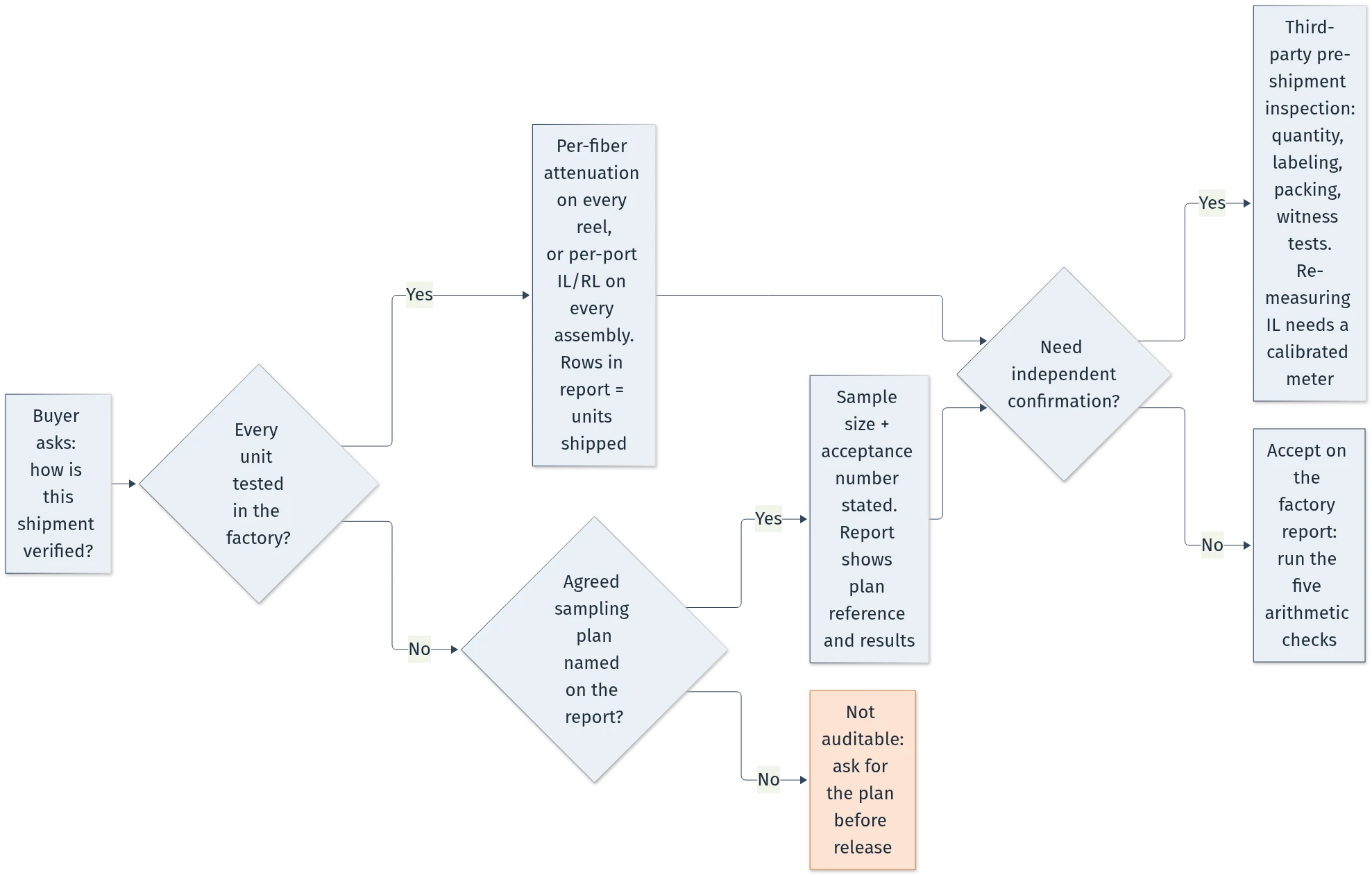
Where the three verification routes sit: full testing inside the factory, sampling against an agreed plan, and independent inspection at the end.
Sampling is legitimate when the process is stable and the order is large. What makes it auditable is naming the plan: the standard and the acceptance number, the sample size, and the rule for a rejected lot. In practice that means a reference such as ISO 2859-1, or its US counterpart ANSI/ASQ Z1.4, together with an inspection level and an AQL. A report that says "sampled per AQL 1.0" is checkable; one that says "sampled" is not.
Third-party pre-shipment inspection is a different instrument again. An inspector can confirm quantity, labeling, packaging, markings and paperwork, and can witness a factory test. Unless the inspector brings a calibrated loss meter and a defined method, they are not independently re-measuring insertion loss — they are confirming that someone else did. Both services are useful; buying one and expecting the other is how projects end up with a clean inspection report and a failing link budget.
The four claims you are most likely to see, and the evidence that separates a real one from a slogan:
Claim on the report | What it can legitimately mean | Evidence that makes it checkable |
|---|---|---|
"100% tested" — cable | Attenuation measured on every fiber of every reel | Row count equals fibers × reels, and the values are per fiber, not per-reel averages |
"100% tested" — assemblies | Every port of every assembly measured for IL and RL | Row count equals ports × assemblies, with a serial number on each row |
"Sampled per AQL" | A defined sample drawn from the lot and judged against an acceptance number | Plan reference, lot size, sample size and acceptance number all stated |
"Third-party inspected" | Quantity, labeling, packing and paperwork verified; factory tests witnessed | Inspection report that names its scope — and a calibrated meter if IL was re-measured |
At the factory level this is a capability question, not a paperwork question. A supplier that runs 100% pre-shipment testing has to own the instruments to do it: an in-house reliability lab with a programmable temperature and humidity chamber, tensile and insertion-force machines, a 3D interferometer for end-face geometry, an IPX8 pressure tester, plus production IL/RL test stations sized to the daily output. DYS Fiber Optic's reliability lab runs twelve-plus specialised stations — environmental, mechanical and optical — and its connector test methods follow GR-326, with per-shipment IL/RL data coming off the production test stations under its ISO 9001 system. That is the kind of capacity claim you can verify on a factory visit by counting instruments and watching a test run.
Put the report in the purchase order, not in the follow-up email
Everything above is unenforceable if the requirement lives in an email. The report becomes a contractual deliverable the moment the purchase order says so, and the wording does not need to be elaborate.
Supplier shall provide, with each shipment and at no additional cost, a test report per lot covering every fiber, port or assembly shipped. The report shall state the purchase order and work order numbers, part number, cable lot and assembly serial range, quantity tested, wavelengths tested, per-unit insertion loss and return loss in dB, the acceptance limit and limit class applied, the test method and standard reference, the instrument identification and calibration due date, and the name of the inspector approving the report. Data shall be supplied as both PDF and machine-readable CSV. Records shall be retained for a minimum of five years and re-issued on request. Buyer may require re-test of any unit at the supplier's facility, at buyer's cost if the unit passes and at supplier's cost if it does not.
Three clauses in that paragraph do the heavy lifting. "Per lot, every fiber, port or assembly" removes the sampling ambiguity before it starts. "Machine-readable CSV" means you can run the five checks above in a spreadsheet in ten minutes instead of reading a PDF by eye. "Retained for five years and re-issued on request" matters because the moment you need the data is two years later, when a link fails and you are trying to decide whether it is the cable, the splice or the installation.
If your supplier holds TL 9000 in addition to ISO 9001, the measurement culture behind the report is usually stronger, because TL 9000 requires reporting operational performance data to a central repository on an ongoing basis — the difference between a management-system certificate and a measurement regime is set out in TL 9000 versus ISO 9001. It still does not replace your own review of the per-shipment document; it only makes it more likely that the document exists in a consistent form.
The one-page checklist
Run this before you release the next delivery — treat it as a test report template you can hand to a supplier and ask them to fill:
- PO and work order numbers present, matching your order
- Part number, connector type and polish match the specification
- Cable lot and assembly serial range present and traceable to the reel
- Quantity tested stated, and per-unit rows equal that quantity
- Wavelengths match the product class (1310/1550 SM, 850/1300 MM, 1310/1490/1550 splitter)
- Insertion loss reported per unit, with the limit and limit class named
- Return loss reported per unit, with the limit and wavelength stated
- Method and standard referenced (IEC 61300-3-4, IEC 61300-3-6, internal work instruction)
- Instrument ID and calibration due date both present and valid at test date
- Inspector named, report dated and signed
- End-face inspection result attached as supplementary, not as a substitute
- CSV or raw trace files available on request
- Sampling plan stated if not every unit was tested
- Discrepancy procedure known: who re-tests, who pays, what the deadline is
Fourteen lines — thirteen statements the document or the supplier must make, including the sampling plan, plus the discrepancy procedure that decides what happens when a row fails. If a supplier's document clears all of them, you have something you can defend in a project review — and if it clears none of them, you now know exactly what to ask for. When the same order also has to satisfy UL, CPR and Anatel simultaneously, the multi-market compliance checklist covers the certification side that sits on top of this data layer.
DYS Fiber Optic runs 100% testing before shipment under its ISO 9001 quality system, on test stations in its own plant. If you are re-specifying what your current supplier has to deliver, our engineering team can work through the fields above with you and tell you which of them this factory can evidence today.