
Connectors
What Makes a Good Fiber Connector: Reading IL/RL Specs
Two patch-cord suppliers quote the same numbers: insertion loss ≤0.3 dB, return loss ≥50 dB. You buy both, mate them in the same panel, and one channel passes its loss budget while the other needs a re-polish. Nothing was lied about. The two numbers were measured under different conventions, against different criteria, and one of them was an objective rather than a requirement.
"Good" is not a property of a connector the way mass or length is. What makes a good fiber connector is a set of graded promises attached to a measurement method, a test population, and a standard issue — and this guide is about reading those promises. Get the conventions straight and the datasheets become comparable. Skip them, and you will keep buying connectors that are individually fine and jointly wrong.
If you are still choosing between LC, SC, FC, ST and MPO housings, that decision lives in the connector families and polish grades this guide sits inside; this page starts one level down, at the numbers those families are sold on.
Key takeaways
- Insertion loss is a method, not a property. "0.3 dB" can mean a single connector measured against a master cord, a randomly mated pair, or a composite jumper measurement divided by two. The three are not interchangeable, and the third one is written into GR-326 itself.
- Return loss and reflectance are the same measurement with opposite signs. A connector at +50 dB return loss is at −50 dB reflectance. Higher is better, which is why an open endface — around 14 dB — is the worst case, not the best.
- GR-326 grades a population, not a part. Its criteria come in three states — new product, during test, end of test — and in two strengths, requirement and objective. A quotation that borrows an objective and calls it a requirement is telling you something.
- IEC 61753-1 gives you a ladder that compares suppliers directly: Grade B is ≤0.12 dB mean and ≤0.25 dB maximum for 97% of random matings; Grade C is 0.25/0.50; Grade D is 0.50/1.00.
- Two connectors that each pass can still fail together. Endface geometry and endface cleanliness decide the mating, and neither appears on a typical datasheet.
What makes a good fiber connector: three numbers, three conventions
A connector's optical quality reduces to two measured quantities and one geometric condition that decides whether they hold:
Quantity | What it measures | Direction | Where it bites |
|---|---|---|---|
Insertion loss (IL) | Power lost crossing the mated pair | Lower is better | Link budget, reach, channel count |
Return loss (RL) | Power reflected back toward the transmitter | Higher is better | Analog video, 10GBASE-LRM, coherent, OTDR traces |
Endface geometry | Shape of the polished ferrule tip | Inside a window | Whether IL and RL hold after 200 matings |
Everything else on a connector datasheet — housing material, boot color, ferrule diameter, mating cycles — is either identification or a durability claim that feeds back into these three.
The trap is that IL and RL are quoted without their convention, and geometry is usually not quoted at all. So the useful question is never "what is your insertion loss?" It is "which insertion loss — measured how, on how many samples, at which wavelengths, and against which criterion?"
Insertion loss: a number with a method attached
Insertion loss is the drop in optical power when light crosses a mated connection. In a link budget it is one term among many: fiber attenuation, splice loss, connector pairs, and margin. Get the per-pair value wrong by 0.2 dB across six connections and a 400G reach calculation moves by more than a decibel.
There are three ways the same connector ends up with a number on a datasheet, and they differ by roughly a factor of two.
1. Single-ended, against a master cord. The connector under test is mated to a reference jumper of known, very low loss, and the measured attenuation is attributed to the device under test. This is the friendliest convention, and it is what a "master cord" column in a grade table refers to. It answers: how good is this end?
2. Random mating, per mated pair. Two production connectors are mated to each other, the pair's loss is measured, and the statistic is reported over a population. IEC 61300-3-34 defines the procedure. This is the convention that matters to a network, because in the field both ends are production parts. It answers: how good is this end against a typical other end?
3. Composite jumper measurement, divided by two. A patch cord has two connectors. Test equipment sees the sum, not the parts. GR-326 handles this explicitly: for service-life tests on jumper assemblies, measured loss values are divided by two before the criteria are applied, and 3.0 dB is subtracted from each reflectance measurement before the reflectance criteria are applied. The standard then adds a warning that the arithmetic is not a licence to average away a bad end — if one connection of a jumper measures 0.7 dB and the other 0.1 dB, a later composite of 0.8 dB does not become 0.4 dB per end for the purposes of passing.
That third convention is the single most useful thing to know when reading a test report, because it is the one buyers never ask about. A jumper that "passes at 0.35 dB" may be a 0.20 dB end mated to a 0.15 dB end, or a 0.60 dB end mated to a 0.10 dB end. Only per-end data tells you which.
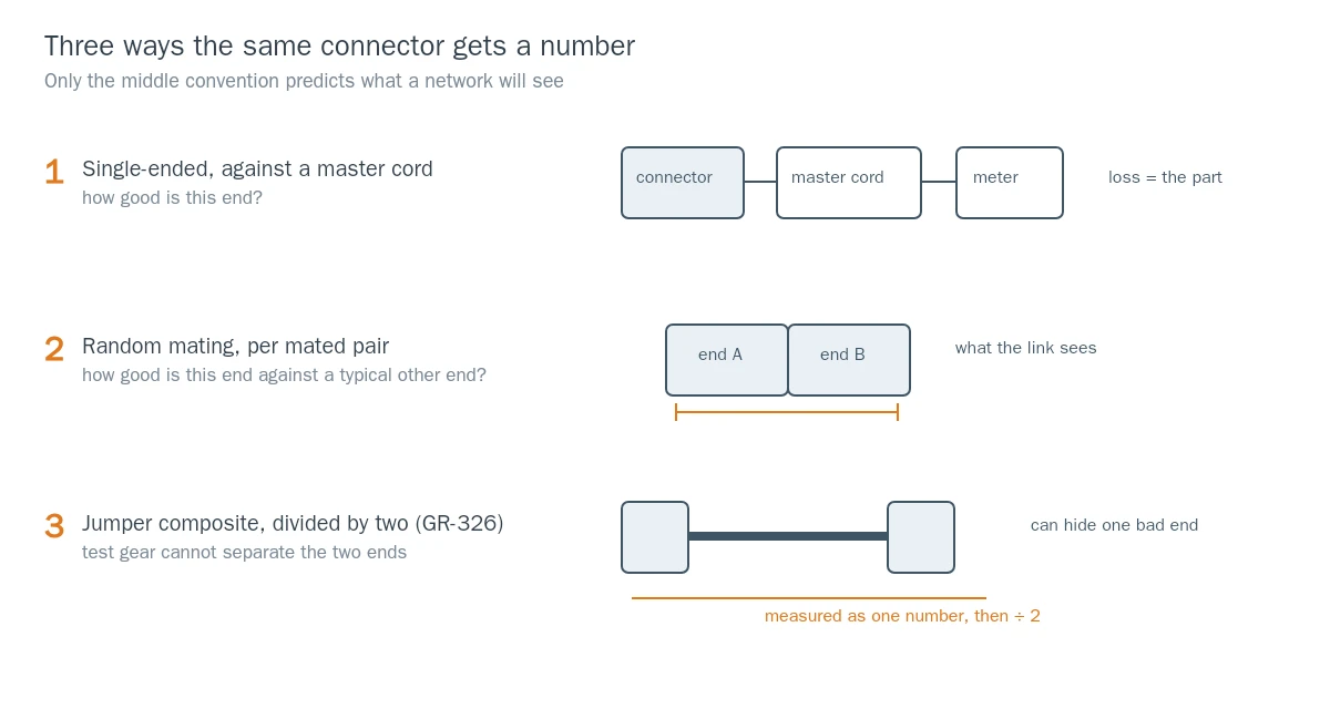
The same connector, three legitimate numbers. Only the middle convention predicts what the network will see.
Two smaller conventions are worth pinning down as well. Wavelength: single-joint connector loss is only weakly wavelength-dependent, and GR-326 requires single-joint optical measurements at both 1310 nm and 1550 nm. A datasheet quoting one figure is usually quoting the worse of the two, but not always. Typical versus maximum: a "typical" value describes a distribution's middle; a "maximum" describes a bound. When a supplier answers a specification question with a typical number, ask for the maximum and the population it came from.
For how IL and RL differ as physical effects — and why a bad cleave shows up in one but not the other — see the difference between insertion loss and return loss.
Return loss: why +50 dB and −50 dB are the same connector
Return loss is the ratio of incident power to reflected power, expressed in positive decibels. Reflectance is the same ratio inverted, expressed in negative decibels. Fluke Networks puts the arithmetic plainly: an open connector endface reflects about 4% of the light, which is 14 dB return loss and −14 dB reflectance. The same event, two signs, and a vocabulary trap in which "high return loss" is good and "high reflectance" is bad.
Three consequences follow.
A higher RL number is a better connector. 50 dB beats 20 dB, and the IEC ladder for single-mode interfaces runs from 26 dB at Grade 4 to 60 dB at Grade 1. Below roughly 45 dB — RL Grade 2 — reflection starts to matter for mainstream digital links such as 10GBASE-LRM. Analog video is held far tighter: GR-326 puts AM-VSB at −55 dB with a −60 dB objective.
Multimode is allowed to be worse. In its review of MPO testing practice, Fluke cites IEC/TR 61282-15 describing single-mode MPO plugs with APC endfaces at better than 50 dB return loss, and multimode MPO plugs with PC endfaces at around 20 dB. That is not sloppiness — short multimode links tolerate reflection that a CATV or coherent single-mode link will not.
The 8° angle is the mechanism. Angled physical contact (APC) polish tilts the endface so reflected light leaves the core rather than travelling back down it. That is why APC parts are specified at 60 dB and UPC parts at 50 dB in single-mode, and why the two must never be mated: an APC-to-UPC connection puts the reflection straight back into the fiber and produces a loss spike that looks like a damaged connector. The APC versus UPC polish comparison covers the geometry and the color codes; the point for a buyer is that RL is a specification you can verify with a meter, and polish type is the main thing that sets the floor.
GR-326 states its reflectance criteria as negative numbers and says so in the text: reflectance is defined as a negative quantity, as opposed to optical return loss, which is positive. If a test report and a datasheet disagree by exactly a minus sign, nobody is wrong — but check which one your acceptance threshold is written against.
GR-326: what the standard actually tests
Telcordia's GR-326-CORE, Generic Requirements for Singlemode Optical Connectors and Jumper Assemblies is the reference most North American carriers and their suppliers write into purchase orders. The current issue is Issue 4, dated February 2010; Issue 3 dates from 1999. Telcordia describes the document as "the most complete and rigorous standard for singlemode fiber-optic connectors," and Issue 4 added endface-geometry discussion, new and updated reflectance criteria, and more detail on salt-spray evaluation.
Four things about its scope decide whether a supplier's claim means anything.
It is single-mode only. Multimode samples are outside the document. A multimode patch cord described as "GR-326 compliant" is either a mistake or a marketing shortcut; multi-fiber assemblies have their own requirement documents, and GR-1435 is the one usually cited for MT-ferrule products.
It covers the adapter, not just the plug. A pigtail assembly in GR-326 terms is two plugs joined by one mating adapter; a jumper is two plugs, one patchcord, and two adapters. Since the adapter's sleeve alignment contributes to the loss, a qualification that only addresses plugs is incomplete.
It grades a population through a sequence, in three states. The optical criteria are applied to new product, to measurements taken during each test (with and without mechanical load), and to measurements at the end of each test. The same connection is therefore judged three times, and "passes GR-326" without a state qualifier is ambiguous.
It distinguishes requirements from objectives. GR-326 labels each numbered criterion: R for requirement, O for objective, CR and CO for conditional variants. Requirements are the pass line. Objectives are the level a good design should reach. Both appear in the tables, side by side, which is exactly how a quotation can end up citing an objective as a specification.
The headline optical criteria, as written in Tables 4-2 and 4-3 of the Issue 3 text:
Criterion | Requirement (R) | Objective (O) |
|---|---|---|
New product maximum loss | 0.40 dB | 0.20 dB |
New product mean loss | 0.20 dB | 0.15 dB |
Mean loss during test, not under load | 0.30 dB | 0.20 dB |
Maximum loss increase during test, under load | 0.50 dB | 0.30 dB |
New product reflectance, digital systems | −40 dB | — |
New product reflectance, analog AM-VSB | −55 dB (conditional) | −60 dB (conditional) |
Reflectance increase, end of test | 5 dB | 2 dB |
Two details make those numbers more useful than they look. First, 0.40 dB was not always the number: the change from 0.50 dB to 0.40 dB arrived with Issue 3 in 1999, so a specification copied from a document older than that is measurably looser than the current criterion. Second, the damage criteria at the end of the test sequence are a permanent loss increase of more than 0.5 dB or a reflectance increase of more than 5 dB, with the polished endface examined at 100× magnification for cracks, chips and scratches. That is the part of GR-326 that separates a connector that tests well on a bench from one that survives a manhole.
Experior Laboratories, which runs these programmes commercially, notes that a full GR-326 qualification "requires dozens of test samples" and assembles them into pigtail and jumper form before the environmental and mechanical sequence begins. That sample population is why GR-326 data is usually reported per family and per process, not per shipment — and why the report, not the badge, is the thing to read. If the assembly you are buying is a pigtail or a jumper assembly in the GR-326 sense, the standard's sample definitions apply directly; if it is a field-terminated plug, most of the service-life sequence does not.
IEC 61753-1 grades: the ladder buyers can actually compare
GR-326 answers "did this product survive a qualification sequence?" IEC 61753-1 answers a different question: "what loss and reflection does this connector deliver when mated at random, and how tightly is that promised?"
The performance standard's general part, IEC 61753-1:2018, sets the categories and the drafting rules for every passive fiber product. The attenuation and return-loss grades themselves appear in the product-part documents and in the grade table that Annex A of the general standard has carried since the 2007 edition, and which IEC 61753-1-3 reproduces as its Table 1 for plug-coupler-plug interfaces. For single-mode connectors, the attenuation grades at 1310 nm and 1550 nm look like this:
Grade | Random-mating mean | Random-mating maximum, >97% of samples |
|---|---|---|
A | not defined | not defined |
B | ≤0.12 dB | ≤0.25 dB |
C | ≤0.25 dB | ≤0.50 dB |
D | ≤0.50 dB | ≤1.0 dB |
Return loss is graded on a separate axis, from Grade 1 down to Grade 4: ≥60 dB mated and ≥55 dB unmated for Grade 1 (the APC case), ≥45 dB for Grade 2, ≥35 dB for Grade 3, ≥26 dB for Grade 4. Attenuation is measured on randomly mated pairs per IEC 61300-3-34; return loss per IEC 61300-3-6; both at 1310 ± 20 nm and 1550 ± 20 nm.
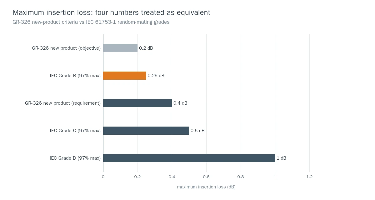
Four numbers buyers treat as equivalent: GR-326's new-product requirement, and the 97% maximum of IEC grades B, C and D. Only Grade B is tighter than the GR-326 line.
Three practical readings of that table.
Grade B is the only grade tighter than GR-326's new-product requirement. A supplier who says "GR-326 qualified" is not automatically a Grade B supplier. Conversely, a Grade B claim is a strong statement about the population, because the 97% clause is a distribution promise, not a single-part measurement.
"97% of samples" is doing real work. It means 3 in 100 random matings may exceed the maximum. For a data hall with thousands of connections, that is a planning input, not a rounding error — and it is why the mean column matters as much as the maximum.
Mating durability has a number too. IEC 61753-1:2018 reduced the mating durability test severity for connectors with cylindrical ferrules in categories C, OP, OP+ and I to 200 cycles, with 50 cycles for rectangular ferrules. When a datasheet says "200 mating cycles," that is usually the standard's test severity being restated as a product property.
Endface geometry: three numbers that decide whether two good ferrules mate badly
Insertion loss and return loss are outcomes. The inputs are the shape of the polished tip. Three parameters describe it, and all three are measured with an interferometer rather than inferred from loss.
Radius of curvature (ROC) is the radius of the best-fitting sphere across the polished area. Too flat and contact pressure spreads; too curved and the fiber sits at the edge of the contact zone.
Apex offset is the distance between the highest point of the polished sphere and the center of the fiber core. A large offset means the two fibers meet off-axis, which raises loss without any visible defect.
Fiber height is where the glass sits relative to the surrounding ferrule — protruding (positive) or recessed, called undercut (negative). Protrusion maintains contact pressure; undercut lets an air gap form, and an air gap is a reflection.
The ranges that recur in qualified single-mode specifications, and that trace back to GR-326's geometry requirements:
Parameter | UPC | APC |
|---|---|---|
Radius of curvature | 7–25 mm | 7–12 mm |
Apex offset | <50 µm | <50 µm |
Fiber height | +50 to −125 nm | +100 to −100 nm |
None of this is visible on a datasheet that only quotes loss. It is also not perfectly reproducible between labs: a NIST-coordinated interlaboratory comparison of endface geometry measurements found small but systematic offsets between participants' radius-of-curvature results, even where most instruments were interferometric. The practical consequence is not that metrology is unreliable, but that your incoming inspection and your supplier's certificate will not agree to the last nanometre, and your acceptance tolerance should be written to allow for that.
Geometry is also where the ferrule itself stops being a commodity. Bore diameter and concentricity set the lateral offset that geometry then has to compensate for; the ferrule bore and concentricity guide covers those tolerances and how they propagate into loss.
Endface cleanliness: the failure mode that is not in the datasheet
A connector can pass geometry, pass loss, and still fail in the panel because a 6 µm particle sat on the core. IEC 61300-3-35 is the standard that makes this inspectable rather than arguable. It divides the endface into zones — A for the core, B for the cladding, C for the adhesive, D for the contact area — and sets pass/fail limits per zone on defect diameter and scratch width.
The 2022 third edition changed the shape of the requirement: inspection requirements for zones C and D were removed, and instead the whole contact area — up to 250 µm diameter for cylindrical ferrules, the entire ferrule surface for rectangular ones — must be inspected for contamination. For single-mode PC connectors the core-zone limits remain the strict ones: the fail lines are a defect larger than 3 µm — one defect between 2 and 3 µm is permitted — and a scratch wider than 4 µm, with up to two scratches between 3 and 4 µm allowed, all inside the 25 µm core zone.
Two things follow for a buyer. First, "visually clean" is not a criterion; the criterion is a zone-by-zone count under a microscope that can resolve 2 µm. Second, a supplier whose visual inspection covers only the core zone, rather than the whole 250 µm contact area, is inspecting to the previous edition.
How to read the test report that comes with the goods
Certificates are cheap. Test data is not. The difference is whether the document lets you reconstruct the measurement.
Ask for these seven fields, and treat a missing one as a question rather than a rejection:
- Which standard and which issue. "GR-326" alone is not enough; Issue 3 and Issue 4 differ on reflectance and geometry content, and the 0.40 dB loss line arrived with Issue 3. The reflectance figures in the table above are the Issue 3 values, so the threshold your PO cites has to name the issue — otherwise you and your supplier may be testing against two different documents.
- The measurement method and reference. Master cord or random mating, single-ended or per pair, and — for jumpers — whether the composite value has been divided by two.
- Wavelengths. 1310 nm and 1550 nm for single-joint single-mode measurements.
- Per-fiber or per-end data, not a single maximum. A 144-fiber trunk summarised as "0.35 dB max" documents nothing you can use at commissioning.
- Population and sampling basis. How many ends, from which lot, sampled or 100% tested.
- Before-and-after values for environmental tests. GR-326 judges new product, during-test and end-of-test separately; a report that only shows a final number has dropped two thirds of the evidence.
- Traceability. Serial or lot identifier linking the report to the goods in the box.
Separately, keep the certification question distinct from the product question. An ISO 9001 certificate describes a management system; TL 9000 adds telecom-specific performance metrics on top of it; neither is a statement about the insertion loss of the parts in your hand. The difference between ISO 9001 and TL 9000 is worth understanding before a supplier's quality certificate is accepted as a product qualification.
A ten-minute incoming inspection you can run yourself
You do not need a qualification lab to catch the failures that matter at goods-in. You need a scope, a meter, and a routine.
Inspect before you measure. Every end, every time, at 200× or better with a probe microscope, checked against IEC 61300-3-35 zones. A dirty end that gets mated becomes a scratched end, and a scratched end does not clean up.
Measure with an OLTS, not a guess. A light source and power meter give you insertion loss per pair in seconds; an OTDR gives you reflectance per event and is the only practical way to see individual connectors inside a long run. The field test procedure covers reference-setting and the bidirectional averaging that keeps the numbers honest.
Sample by risk, not by habit. For a single-mode backbone with a dozen connectors, test every end. For a 5,000-piece drop-cable order, a documented AQL sample with per-end data is enough to catch a process shift — provided you also measure at least a few ends from every carton, because polishing drift tends to be batch-shaped.
Record what you measured and against what. The number without the convention is not evidence. A line in your receiving log reading "0.22 dB, random mating, 1310 nm, master cord serial 4471" is a datum; "passes" is an opinion.
Where a manufacturer's own datasheet sits in this
A well-built datasheet is a compressed version of everything above, and it should let you place each row in one of the three conventions. Here is a real example from our own catalogue, for the IPFX outdoor assembly, read the way this article has taught you to read it:
Row | Value | What it tells you |
|---|---|---|
Insertion loss, SM-UPC | ≤0.15 dB typical / ≤0.30 dB max | Both bounds given, so you can budget on the max |
Return loss, SM-UPC / SM-APC / MM-UPC | ≥50 / ≥60 / ≥30 dB | APC floor is 10 dB better, as the 8° angle implies |
Durability | 200 cycles | Matches the IEC 61753-1 mating-durability severity |
Standards referenced | IEC 61753-1, IEC 61754-4 | Performance and interface standards named separately |
What is missing from that table is as instructive as what is in it. It does not state a measurement convention for the loss figures, which is normal for a catalogue page and is exactly why a per-assembly test report is the document to request with the order. If you are specifying IP67 outdoor assemblies for FTTA or small cells, the DYS connector range is built against those interface standards; the useful conversation is about which report you will receive, not which badge is printed.
Spec traps worth memorizing
The claim you will hear | The question that resolves it |
|---|---|
"Insertion loss 0.3 dB" | Per connector against a master cord, or per randomly mated pair? |
"GR-326 compliant" | Issue number, which state (new/during/end of test), and requirement or objective? |
"Grade B connector" | Mean and 97% maximum, measured per IEC 61300-3-34 at both wavelengths? |
"Return loss 55 dB" | Return loss (+dB) or reflectance (−dB) — and is the acceptance threshold written the same way? |
"Low loss MPO" | Per-fiber maximum, or per-connector aggregate? |
"200 mating cycles" | Test severity or field-life claim — and under which IEC category? |
None of these questions requires a lab. They require knowing that the number on the page has a convention behind it, and that the convention is where the difference between two "0.3 dB" connectors actually lives.