
Connectors
Legacy FC vs ST Connectors: What Replaces Them
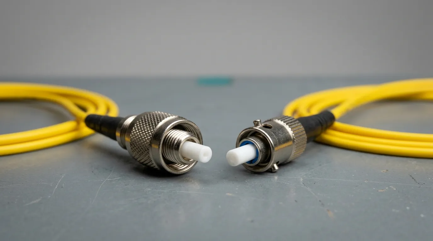
FC and ST are the two 2.5 mm single-fiber interfaces that most networks inherited instead of choosing, and they did not age the same way. ST — the bayonet type AT&T introduced and the IEC now standardises as BFOC/2.5 — is a dead end: it was built for multimode datacom, it never became an angled-polish product in the mainstream catalogue, and nothing in its design leads anywhere denser. FC — the threaded type that came out of NTT — is not: its screw coupling holds where a bayonet can loosen, and FC/APC is a real, stocked family. That asymmetry is the whole answer to "fc vs st connectors": ST gets replaced, FC sometimes gets kept.
The version of this question that matters in a real project is not which connector is better. It is what you do with the plant you already own — the ports, the panels, the ODF bays and the test bench that were specified around one of these two interfaces fifteen or twenty years ago, and the new electronics that will not plug into them. And to answer the question that brings most people here in the first place: yes, ST connectors are still made, still standardised and still in stock. They are legacy, not obsolete — which is a different problem, and a harder one to price.
So this comparison runs on the dimensions that decide that: the coupling, the failure modes it produces, the polish each family can reach, the density ceiling both of them hit, and the replacement hardware that lets you change one end of a link without touching the cable. If you need the wider family first — LC, SC, FC, ST and MPO side by side — start with our guide to fiber optic connector types and come back; everything below assumes you already know which connector is in your hand.
FC vs ST Connectors at a Glance
Neither interface is obsolete in the standards sense. The IEC still publishes both — FC as IEC 61754-13, ST as IEC 61754-2 — and both remain orderable. What has changed is where each one is allowed to sit in a modern network.
FC connector | ST connector | |
|---|---|---|
Full name | Ferrule Connector (also written Fiber Channel) | Straight Tip; standardised as BFOC/2.5 |
Interface standard | IEC 61754-13, "Type FC-PC connector family" | IEC 61754-2, "Type BFOC/2,5 connector family" |
Coupling | M8×0.75 thread, knurled nut, single alignment key | Bayonet: push in, twist about half a turn |
Ferrule | 2.5 mm ceramic, spring-loaded on the optical axis | 2.5 mm ceramic, spring-loaded |
Polish in the mainstream catalogue | PC, UPC and APC (FC/APC) | PC and UPC; APC is not a standard catalogue item |
Typical mated-pair insertion loss | 0.25–0.5 dB | 0.25–0.5 dB |
Return loss floor, PC polish | Around 50 dB | Around 50 dB |
Rated mating cycles | ~500 | ~500 |
Historic home | Singlemode telecom, test equipment, polarisation-maintaining fibre | Multimode datacom, campus LAN, military |
What replaces it | LC at the port, SC/APC in outside plant; FC often survives at the test bench | SC, then LC — usually through a hybrid adapter rather than a re-termination |
Read the insertion-loss, return-loss and mating-cycle rows together and the pattern appears. The optical performance is a tie — both are 2.5 mm ceramic-ferrule spring-loaded interfaces, so both land in the same loss band. Everything that separates them is mechanical, and mechanics is what decides whether a 20-year-old plant can be kept.
Two 1990s Interfaces That Only Look Alike
At a glance an FC and an ST connector are easy to confuse: both are cylindrical, both are metal-bodied, both expose a 2.5 mm ceramic ferrule at the tip, and both carry a single fibre. The ST bayonet collar and the FC knurled nut even sit in roughly the same place on the barrel.
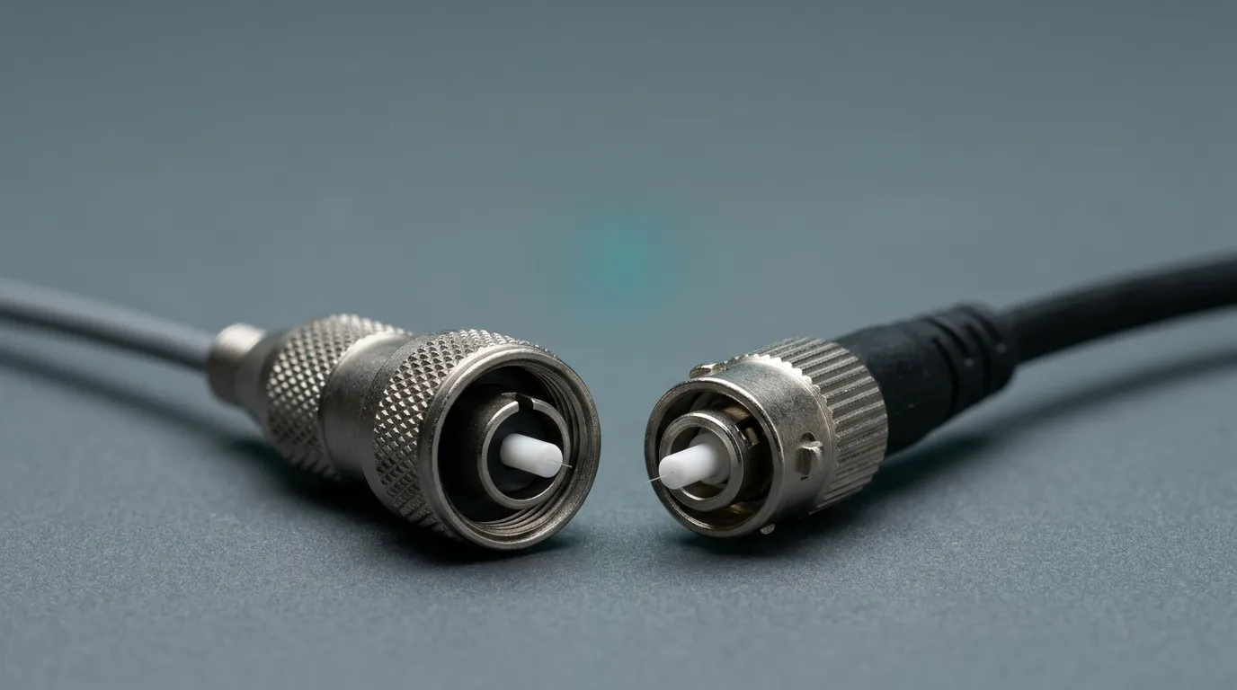
Left, the FC's knurled coupling nut and internal thread. Right, the ST's bayonet collar with its radial lugs and a rubber boot.
Their origins diverged from the start. The FC came out of NTT in Japan and became one of the most popular singlemode connectors for many years. The ST came from AT&T shortly afterwards and went the other way — into multimode datacom. The Fiber Optic Association's connector reference still describes the ST as "probably still most popular connector for multimode networks until ~2005." That single sentence explains most of what follows: ST's installed base is multimode, and multimode campus plant is exactly where re-cabling is hardest to justify.
The naming is worth pinning down, because it trips people up in RFQs and in search results. ST stands for Straight Tip, a trade name; the actual interface standard calls the family BFOC/2.5, which is why an engineer may talk about "ST" while a drawing says BFOC. FC stands for Ferrule Connector, and is also written out as Fiber Channel.
What the standards fix is narrower than people expect, and more useful. IEC 61754-13 defines the FC family as a single-position plug-and-adaptor set built around a 2.5 mm nominal ferrule, with a thread screw coupling sprung against the ferrule on the optical axis, a single male key, and a spherically polished endface that achieves physical contact. IEC 61754-2 does the same job for BFOC/2,5 — and its current edition is recent enough (2026) to make the point that "legacy" describes the installed base, not the paperwork.
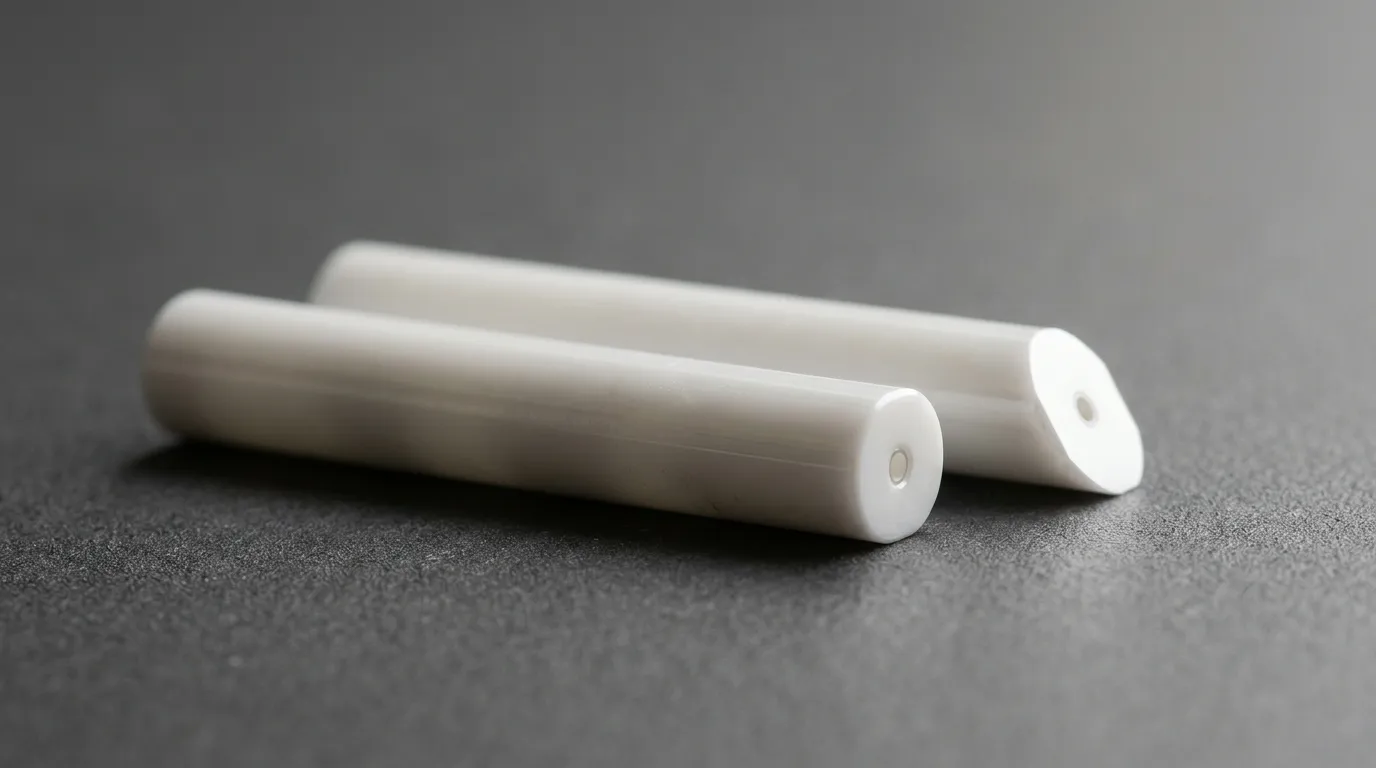
The shared 2.5 mm ferrule is the detail worth remembering. It is also the part doing the actual work — the ceramic ferrule is where the alignment tolerance budget lives — and because both interfaces use the same one, it is what makes every migration in the second half of this article possible without pulling cable.
The Coupling: M8 Thread vs Bayonet, and What Each One Costs You
The mechanical difference is small enough to describe in one sentence and large enough to determine how a network behaves. FC threads on. ST pushes and twists.
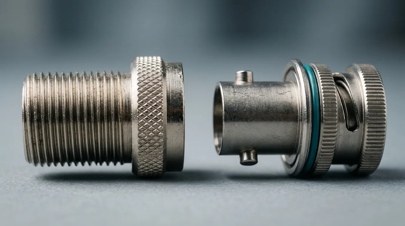
The FC barrel (left) carries a fine M8×0.75 thread; the ST barrel (right) carries two radial lugs that ride into a bayonet slot.
On an FC, the thread is M8×0.75 and the barrel carries one key that must drop into a slot on the adapter before the knurled nut is tightened. Get the key right and the coupling pulls the ferrule forward against its spring until the two endfaces are in physical contact; the thread then holds that load for as long as it stays torqued. There is no spring-loaded release and no latch to pop open — the only way that coupling comes apart is if something unscrews it. Get the key wrong and you are forcing a ceramic ferrule against a metal stop — which is how endfaces get scratched before the connector has ever carried traffic. The FOA's field note is blunt about the discipline required: the FC "screws on firmly, but you must make sure you have the key aligned in the slot properly before tightening."
On an ST, you align the key, push, and twist roughly half a turn until the lugs seat in the bayonet slot. It is faster, it needs less dexterity in a glove, and it gives a positive "it clicked" signal that a thread does not. It also has one characteristic nobody designs for and everybody meets: because the coupling is spring-loaded, a connector that is almost seated looks seated.
The field diagnostic that tells the two failure modes apart. The FOA's troubleshooting advice for ST links is a single sentence — "If you have high loss, reconnect them to see if it makes a difference" — and it generalises: on an ST link, a high loss reading is a seating problem until proven otherwise, so reseat and re-test before you touch anything else. On an FC link, a high loss reading after a fresh install is an endface problem until proven otherwise.
That difference in failure signature matters more than the difference in mating time. A bad FC connection usually announces itself as a link that never came up, or as an endface you can see is damaged. A bad ST connection announces itself as a link that came up and then drifted — which is why ST trouble tends to be found by an OTDR trace weeks later rather than at installation.
Where Each One Fails in the Field
Four failure modes account for most of the trouble these two interfaces cause, and they are not symmetric.
ST: seating, and the absence of a positive lock. A bayonet collar resists axial pull reasonably well when it is fully engaged, but it is not a latch and it is not immune to being wiggled. A partially rotated collar leaves the ferrule under-seated — loss creeps up, and the connector still looks installed. In panels that get touched during adds and moves, this is the single most common cause of a "bad port" that turns out to be a bad mate.
ST: no density path. A 2.5 mm ferrule in a round metal body is, mechanically, the largest single-fibre footprint of the five common connector families. Nothing about the design can be shrunk without becoming a different connector.
FC: key alignment and endface damage. The single key is a hard stop. Insert off-key and the ferrule tip can contact metal before it enters the alignment sleeve. This is a handling error, not a design flaw, but it is a handling error the design makes possible, and it is why FC installs are typically done by people who have done them before.
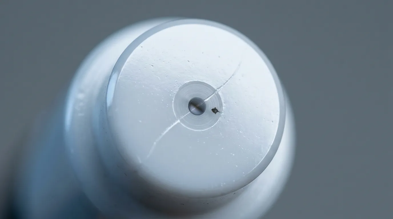
One off-key insertion is enough. A scratch across the core does not heal, and cleaning will not remove it.
FC: the thread backs off, or it does not. Here the published record contradicts itself, and it is worth saying so plainly rather than picking a side. A published FTTH-equipment comparison describes the FC's screw collet as "particularly effective in high vibration environments, ensuring that the spring-loaded ferrule is firmly mated." The connector reference entry that draws on the FOA's material, on the other hand, advises that an FC "should not be used in vibrating environments due to its threaded lock." Both statements are about the same piece of hardware, and both are defensible once you separate the two conditions they describe: a thread that has been properly torqued holds a preload very well, and a thread that has only been snugged by hand is the one that walks loose under thermal cycling and vibration — with no secondary lock to catch it. If vibration is in your specification, FC is usable only with a stated torque and a periodic check; if you cannot guarantee the torque, a latch connector is the honest answer.
Neither interface is the fragile one; they punish different mistakes at different times.
Polish Is Where the Two Stop Being Equivalent
This is the section that decides whether the connector in your hand has a future, and it is the part almost every comparison skips.
Physical contact polish comes in three practical grades. PC is a slightly domed endface that brings the two fibre cores into contact. UPC is the same geometry held to a tighter dome and finish, which lowers reflectance. APC grinds the endface at an angle — normally 8°, with 9° used for SC/APC in some countries — so that light reflected at the glass-to-glass interface leaves the core and is lost in the cladding instead of travelling back up the fibre.
Grade | Endface geometry | Return loss | Where you meet it |
|---|---|---|---|
PC | shallow spherical dome | around 50 dB on an ST-class part | legacy FC and ST patch cords |
UPC | same dome, tighter finish | lower reflectance than PC | current LC and SC patch cords, usually blue |
APC | 8° angle, 9° on some SC/APC | stays low even when the far end is disconnected | PON, RF video, high-power launch — green |
An APC vs UPC comparison covers the reflectance arithmetic; for this article the relevant consequence is narrower: APC keeps return loss low even when the far end of the fibre is disconnected, which is why access networks, RF video overlay and any high-power launch specify it rather than hope for it.
You can read polish off the hardware. The TIA-568 colour convention is beige for multimode, blue for singlemode and green for singlemode APC. There is a wrinkle specific to these two connectors: the FOA notes that "the advent of metallic connectors like the FC and ST made color coding difficult, so colored boots were often used." On an FC or an ST panel, look at the strain-relief boot, not the body.
A square PC endface (left) reflects light straight back into the core. An angled APC endface (right) reflects it out into the cladding — drawn steeper than the 8° a real part is ground to, so the geometry is visible.
FC got APC. ST never got one as standard. An angled FC connector is a stocked part — designated FC/APC, or sometimes just FCA — and the connector reference documents two variants that do not interoperate: FC/APC-N with a 2.14 mm key (the NTT pattern) and FC/APC-R with a 2 mm reduced key. An FC/APC-N plug will not enter an FC/APC-R adapter slot, and a mismatched pair either fails to mate or loses angular alignment. That is a real inventory trap.
ST's mainstream catalogue stops short of APC: a current ST product specification lists a 2.5 mm zirconia ferrule, service life of 500 mating cycles, standard insertion loss of 0.2 dB typical and 0.4 dB maximum, and a PC return loss minimum of 50 dB — then marks ultra-low-loss and low-loss compatibility as not available. That is the manufacturer's own data sheet, not an inference. The same equipment supplier quoted above puts it just as directly — ST "cannot be terminated with an angled polish, which limits its use in single-mode fiber and FTTH applications" — and it is worth being precise about what that means. Angled ST assemblies do get built to order, so this is a statement about mainstream supply rather than about physics: what ST lacks is an angled variant with a standardised endface geometry, a standardised return-loss floor and a mating guarantee. For a new link with an APC specification, that is the same as not existing.
Put those two facts together and the asymmetry in the title resolves. Any link with an APC return-loss requirement rules ST out as a catalogue part: an angled ST is a build-to-order special rather than a standardised polish variant, so it carries no standardised return-loss grade and no intermateability promise you can specify against. FC does not have that problem. That is why FC survives in outside-plant and test contexts where an APC interface is mandatory, and why ST's remaining territory is PC-polished multimode — a shrinking island.
The Density Math That Retired Both
If polish explains why ST has no future and FC has a small one, density explains why neither is the default anymore.
Everything scales from the ferrule. A 2.5 mm ferrule needs a 2.5 mm alignment sleeve, which needs a housing wide enough to hold it, which sets the pitch of adapters in a panel and the footprint of a duplex pair. Shrink the ferrule to 1.25 mm — the LC — and the whole stack halves: duplex LC occupies roughly the space of an RJ45 jack, and a panel that holds 24 duplex SC or FC ports will typically hold about 48 duplex LC ports. The LC vs SC comparison works through the ferrule geometry; FC and ST sit on the same side of that ledger as SC.
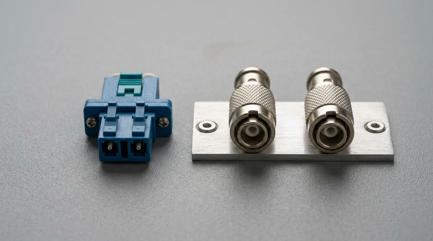
The same two fibres on each side. The LC pair on the left takes a fraction of the panel width two bayonet adapters need on the right.
Then the electronics finish the argument. SFP and SFP+ transceivers — the format that has carried most serial optical links for two decades — take duplex LC in datacom applications, so the port side of a link is LC no matter what the cable plant is. Above that, parallel optics break out to MPO: IEC 61754-7 defines a ferrule carrying 4 to 24 fibres in one interface, with singlemode versions angled for the same reason APC exists. And the current step beyond MPO is the very-small-form-factor pair, MDC and SN, which put three connectors into the panel cutout that previously held one duplex LC.
Neither FC nor ST appears anywhere on that curve. This is the honest reason the question is phrased as "what replaces them" rather than "which should I choose": for new ports, the choice was made by the transceiver and the panel cutout years ago.
Cost follows the same shape, and needs no price list to be useful. The drivers are the labour to terminate each end, the panel and adapter hardware that has to change alongside the connector, and whether the cable itself has to be re-pulled. FC and ST both sit high on the first two and, in a legacy plant, low on the third — which is exactly why hybrid hardware changes the economics as much as it does.
What Replaces Them, Port by Port
There is no single successor, because the two interfaces were never doing one job. Work through the locations instead.
Where the old connector sits | Replace with | Why |
|---|---|---|
Datacom switch, router or media-converter port (SFP/SFP+) | Duplex LC | The transceiver defines the interface; SFP and SFP+ optics ship with LC receptacles |
Parallel-optics port (QSFP 40G-SR4, QSFP28 100G-SR4, QSFP-DD) | MPO-12 or MPO-16, fanned out to LC | These ports are multi-fibre by design, not duplex — the same reason the trunk moves to MPO |
Outside plant, FTTH/ODN, or any bay with an APC return-loss spec | SC/APC | Keeps the 2.5 mm ferrule, gains push-pull field handling and a standard APC interface |
Trunk between racks, ODF to ODF, or high-count riser | MPO/MTP 12 or 24 fibre, fanned out to LC | One ferrule carries 12–24 fibres instead of one |
Test bench, OTDR port, power meter, reference jumper | Keep FC (FC/APC where return loss matters) | Instrument receptacles are commonly FC; every adapter you add inserts another mating pair and its loss |
Legacy multimode campus panel you are not replacing | ST-to-LC hybrid adapters plus LC patch cords | No re-termination, no cable pull, electronics side modernised |
Two rows in that table come from the same physical fact: FC, ST, SC and the older FDDI and ESCON connectors all use a 2.5 mm ferrule, so they "can be mixed and matched to each other using hybrid mating adapters." An adapter is a single part with one interface on each face — the same adapter and coupler hardware used to join any two connectors built on one ferrule size. An ST-to-LC hybrid adapter accepts a bayonet plug on the front and an LC plug on the back, which means the panel you cannot afford to touch can stay exactly where it is while everything downstream becomes LC.
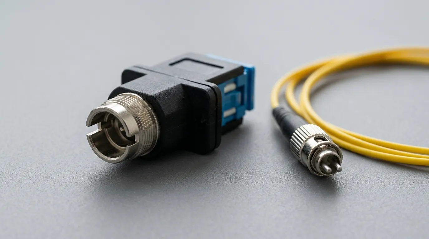
One part, two interfaces: a bayonet socket on one face and an LC socket on the other. This is the cheapest migration path in a legacy plant.
If you keep one rule from this section. A panel you cannot touch gets a hybrid adapter. A panel you are replacing anyway gets LC or SC/APC, whichever the new electronics wants. A port on a transceiver is already LC, because the transceiver decided that before you arrived.
The same logic produces hybrid patch cords — an ST plug on one end and an LC plug on the other, sold as an "ST to LC patch cord" — which is the part to search for when a single run has to cross the boundary. It is also the most commercially intentful query in this topic — the people typing it are not reading, they are ordering.
The cable end itself gives you a second decision, separate from the panel. You can re-terminate the existing fibre with a field-installable connector, or you can fusion-splice a factory-made pigtail onto it and plug the new LC or SC end. Re-termination is cheaper per end but puts the polish and the proof in the technician's hands at every end; pigtail splicing keeps the factory endface and the factory test record on the end that matters, at the price of a splice and its loss in the budget. On a campus plant that already has splice enclosures, the pigtail route is the one that puts a tested endface into the link.
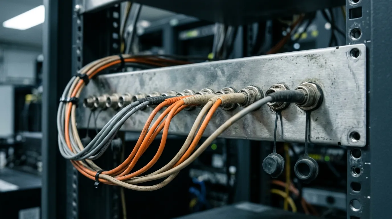
A 1990s-era bayonet panel. The metal bodies carry no colour code, so polish has to be established from the boots or the documentation before ordering anything.
Before you order, establish what polish you already have. On a metal-bodied FC or ST panel the TIA-568 colour code does not help, and the failure mode of getting it wrong is severe: an angled connector mated to a flat one produces very high insertion loss, not a marginal degradation. Check the boot colour and its printed legend; if neither is legible, put a scope on one endface before you commit to a part number.
Keeping FC, and When Not to Keep ST
Each of these interfaces still has a location where it is the correct answer.
Keep FC where the instrument or the alignment is the constraint. OTDR ports, optical spectrum analysers, power meters and reference jumpers are commonly FC — and where they are, it is because the threaded coupling does not move once set, and because a test port gets mated thousands of times by different hands. Polarisation-maintaining fibre is the second case: PM links depend on angular alignment being held, and the FC key plus thread does that better than a latch. Industrial cabinets where every connection is torqued and inspected on a maintenance schedule are the third. If your link is FC and your bench is FC, converting the link to LC is reasonable; converting the instrument port is not — you would be adding an adapter and a mating pair to save nothing.
Keep ST only where the panel is the constraint. This is a narrower case than vendors admit, but it is real: an installed multimode campus plant whose panels are bayonet, carrying links that are not being upgraded, is cheapest to keep running with ST-to-ST patch cords. Ripping out serviceable panels to gain a connector generation is not an upgrade — it is a project with a cost and no functional return. Note what this case is not: it is not an argument for specifying ST on anything new, and it is not an argument for ST anywhere an APC return-loss spec applies, because an angled ST is a build-to-order special with no standardised return-loss or intermateability promise to design against.
Do not keep ST where any of these are true: the link needs APC; the panel is being replaced anyway; the port count is growing; or the run is singlemode and headed for FTTH or ODN duty. In each of those, the ST is the thing standing between you and a modern interface, and a hybrid adapter only postpones the decision.
And the same test applied honestly to FC: if your FC bay is a high-count singlemode ODF feeding access equipment, FC is not being kept for a technical reason — it is being kept because nobody has priced the panel swap. Hybrid adapters will carry you across that boundary when the time comes.
What to Write in the RFQ When You Swap
The reason legacy swaps go wrong is rarely the connector. It is a specification that says "LC" and nothing else. Five lines close that gap.
- Interface, by standard number. LC is IEC 61754-20, SC is IEC 61754-4, MPO is IEC 61754-7, FC is IEC 61754-13, BFOC/2.5 (ST) is IEC 61754-2. Naming the standard removes the ambiguity between "LC" and "LC-compatible."
- Polish and colour, together. UPC on a blue body or APC on a green body — and for an FC, which key width, since FC/APC-N and FC/APC-R do not mate.
- Insertion loss per mated pair, with the test method. A number without a method is not a specification. If you are contracting to a return-loss floor as well, state it here; insertion loss and return loss are measured differently and fail differently.
- Ferrule grade and endface acceptance. Grade affects both loss and the yield of the assembly; an endface geometry acceptance criterion is what stops a marginal polish from shipping.
- Per-assembly test data with serial traceability. For a refit across hundreds of ports, the test record is what lets you find the two bad ends without re-testing everything.
If your operator contracts to Telcordia GR-326 generic requirements for singlemode connectors and jumper assemblies, say so in the RFQ rather than assuming the supplier's default applies — that document is where the environmental and endurance expectations live, and it is the reference that separates a carrier-grade assembly from a commercial one.
DYS builds patch cords and assemblies to a stated interface, polish and loss budget rather than to a catalogue part number, including hybrid cords that bridge an old bayonet or FC panel to LC electronics. If the refit in front of you needs a part that does not exist in anyone's catalogue, send us the interface spec and we will tell you whether it can be built.
Bottom Line
ST and FC share a ferrule, a loss band and a decade, and that is where the similarity ends: ST was built for multimode datacom and has no path to APC or density, while FC's thread and its FC/APC family keep it legitimately alive at the test bench and in PM work. For everything else, the replacement is LC at the port, SC/APC in outside plant and MPO in the trunk. Because SC/APC shares the 2.5 mm ferrule with FC and ST, an outside-plant or panel-end conversion can usually be made with a hybrid adapter instead of at the cable — whereas a trunk moving to MPO is a re-cable of that trunk, not a panel change. If you are still mapping the family as a whole, the fiber optic connectors hub collects the type, polish and performance guides in one place.